

1. Introduction
2. Experiment
2.1 Catalyst preparation
2.2 Experimental setup
3. Results and Discussion
3.1 Characterization of the Catalyst
3.2 Reactivity of catalysts at N2O decomposition
3.3 Hot-fire test of N2O monopropellant thruster
4. Conclusion
1. Introduction
A small satellite is more economical for Low Earth Orbit (LEO) mission than a large one because of less aerodynamic drag and reduced cost of launching [1]. A propulsion system for a small satellite requires high thrust with low power consumption for drag compensation and station keeping. Cold-gas thrusters, electrothermal thrusters, and monopropellant thrusters are available for the propulsion system. However, cold-gas thrusters have low specific impulse. Electrothermal thrusters require a large heating device in order to heat propellant to high temperature; thus, high power consumption is inevitable. Monopropellant thrusters are suitable for a small propulsion system because additional power supply is not required after the startup: propellant decomposition is self-sustained on the catalyst after initiation.
Hydrazine (N2H4) has been mostly used as a monopropellant; however, it is very toxic and is of hazard in storage and handling. Recently, eco-friendly monopropellant thrusters have been developed such as nitrous oxide (N2O) and [2,3] hydrogen peroxide (H2O2) [4], which are called “Green propellants.” Among these propellants, non-toxic N2O propellant has a large storage - temperature range between critical point (-90.8°C) and decomposition temperature (520°C). It shows also good liquefaction characteristics: N2O exists in a liquid state over 52 atm at 21°C. N2O is pressurized in a storage tank (over 52 atm); thus, a propellant supply system is not required. Since characteristics of N2O are relatively safe in storage and handling, development and maintenance expenses of N2O thruster are significantly reduced. Furthermore, N2O is very stable and easy to handle at room temperature, and easily available in industrial quantities [2]. Physical characteristics of N2O are presented in Table 1.
Table 1.
Physical characteristics of nitrous oxide
N2O decomposes into nitrogen and oxygen, generating decomposition heat of 82 kJ/mol as shown in Eq. (1)[5]. N2O decomposition process generates high temperature gases that are used for various propulsion applications such as monopropellant thrusters, rocket igniters, power generation devices, and auto-ignition for bipropellant and hybrid rockets [6,7].
It is reported that N2O is thermally decomposed at temperature higher than 520°C [2]. In actual propulsion system, however, the temperature should be higher than 1000°C. Thus, N2O thermal decomposition requires a big heating device with the high-power consumption. Zakirov et al. [2] reported that N2O decomposition on the proper catalyst was possible at temperature less than 300°C. Additional heat supply was not required because N2O decomposition was sustained by the reaction heat after the reaction was initiated. However, adiabatic decomposition temperature of N2O is 1640°C; thus, the catalyst becomes damaged during N2O decomposition. Therefore, a heat-resistive and durable catalyst for N2O decomposition is required for practical applications. Alumina (Al2O3) is widely used as a catalyst support for the N2H4 and H2O2 decompositions [4]. However, Al2O3 is sintered at 1000°C; thus, its specific surface area rapidly decreases due to phase transformation, resulting in deactivation of the catalyst active sites [8]. Courtheoux et al. [9] studied catalytic decomposition of hydroxylammonium nitrate (HAN) on platinum (Pt) supported on silicon-doped alumina (Si-Al2O3). The Pt/Si-Al2O3 catalyst remained active with a fast reaction rate during the HAN decomposition. Zeng et al. [10] studied catalytic decomposition of N2O on alumina-supported ruthenium (Ru/Al2O3) catalysts. The optimum Ru loading was found and the catalytic activity was measured at the various reaction conditions. Boissel et al. [11] studied noble metal-transition metal oxide catalysts supported on cordierite monolith for N2O decomposition. The effect of combination of transition metal (Cu, Fe, Co, Ni) and noble metal (Ir, Rh) was investigated.
Al2O3 has been widely employed as a catalyst support by numerous researchers due to its high specific surface area, excellent thermal stability, and mechanical robustness, which make it well-suited for various catalytic applications. However, Al2O3 exhibits a temperature-dependent phase transformation pathway, beginning with the transition from the γ-phase (typically stable below ~800°C), progressing through intermediate phases such as δ-, θ-, and β-Al2O3, and ultimately converting to the thermodynamically stable α-phase at temperatures above ~1100–1200°C. These phase transitions are influenced by factors such as heating rate, precursor characteristics, and dwell time during thermal treatment. In the present study, a Ru catalyst supported on Si-doped Al2O3 was prepared for N2O decomposition. Si was doped into the Al2O3 support in order to improve heat-resistivity at high temperature. The effect of Si addition on Al2O3 surface structure and N2O decomposition was investigated and a subscale N2O monopropellant thruster was designed and tested.
2. Experiment
2.1 Catalyst preparation
Ru metal element was selected as a catalyst for N2O decomposition. The catalyst support was γ-Al2O3 that provides a large surface area with good thermal-stability [4]. Si was loaded into γ-Al2O3 support in order to improve heat-resistivity at high temperature. The detailed procedure of catalyst preparation is as follows. First, pellet-shaped γ-Al2O3 support (Alfa Aesar, 1/8” pellets) was used because it is easy to pack the thruster chamber with pellets. Si was doped into γ-Al2O3 pellets using wet impregnation method. (C2H5O)4Si (Alfa Aesar) was used as precursor. After drying at 120°C for 12 hours, the pellets were heated at 1200°C at air environment: the temperature was raised up with 10°C/min and maintained for 2 hours. We obtained Si-doped Al2O3 (Si-Al2O3) with Si content of 5 mol%. Subsequently, Ru was loaded into Si-Al2O3 using wet impregnation method. RuCl3 (KOJIMA) was used as precursor. The prepared catalyst pellets were calcined at 700°C after complete drying. Consequently, Ru/Si-Al2O3 catalyst was obtained. Ru loading was 5 wt%.
Table 2.
Preparation conditions of the catalyst
| Sample name | Catalyst | Ru (wt%)a | Si (mol%)b |
| A | Al2O3 | - | - |
| SA | Si-Al2O3 | - | 5 |
| RA | Ru/Al2O3 | 5 | - |
| RSA1 | Ru/Si-Al2O3 | 5 | 5 |
| RSA2 | Ru-Si-Al2O3 | 5 | 5 |
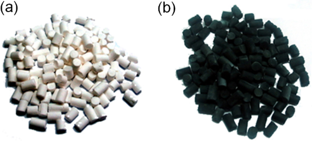
All prepared catalysts including Al2O3, Si-Al2O3, Ru/Al2O3, Ru/Si-Al2O3, and Ru-Si-Al2O3 are listed in Table 2. Fig. 1 shows bare γ-Al2O3 and the prepared Ru/Si-Al2O3 catalysts. For comparison purposes, bare γ-Al2O3 pellets without Si doping were heated at 1200°C and Ru/Al2O3 was prepared using conventional method. Another catalyst was prepared using a different method. Ru and Si precursors were simultaneously loaded into γ-Al2O3 pellets, while element contents and heat-treatment conditions were the same as with Ru/Si-Al2O3 catalyst. The catalyst was named Ru-Si-Al2O3. All catalysts were characterized using SEM (Scanning Electron Microscopy), EDS (Energy Dispersive X-ray Spectroscopy), and XRD (X-Ray Diffractometer).
2.2 Experimental setup
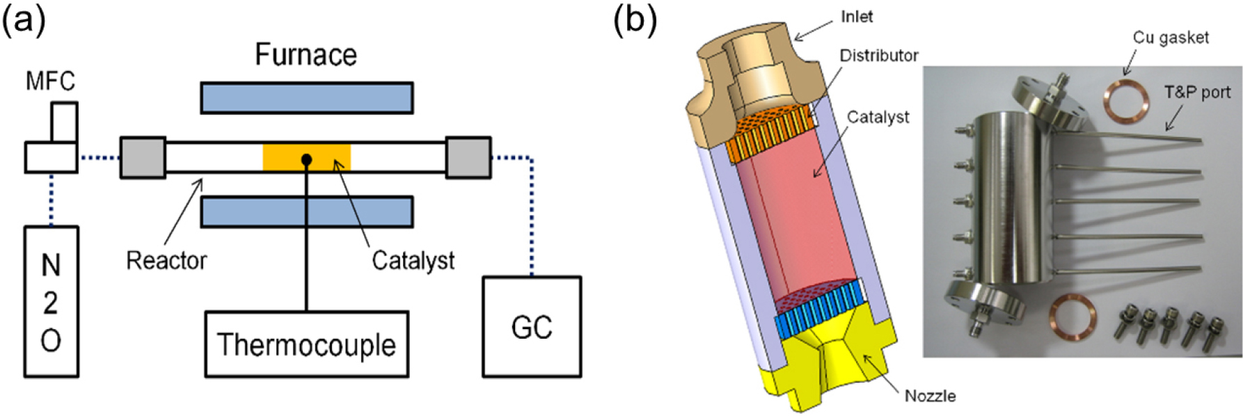
Experimental apparatus for N2O decomposition on the prepared catalysts is shown in Fig. 2(a). The prepared catalyst was fixed into a quartz tubular reactor. The N2O feed rate was controlled using MFC (BRONKHORST). The reaction temperature was controlled using a programmable electric furnace. A thermocouple was inserted at the middle of the catalyst in order to measure the temperature during the reaction. A subscale monopropellant thruster is shown in Fig. 2(b). The 2-piece flanges were sealed with copper crush gasket. The optimal catalyst selected in the N2O decomposition testing was packed in the thruster chamber. The thruster chamber volume was 30 ml where 15 g of catalysts were filled. The temperature and pressure ports were welded on the thruster as shown in Fig. 3. 5 thermocouples were inserted through the connecting ports and the tips protruded to the chamber centerline. The catalyst was supported on the up and down sides with porous metal discs [12].
The gas chromatography (YOUNGLIN, YL6100) was used to analyze product gas composition such as N2O, N2, and O2. The N2O conversion is defined as Eq. (2).
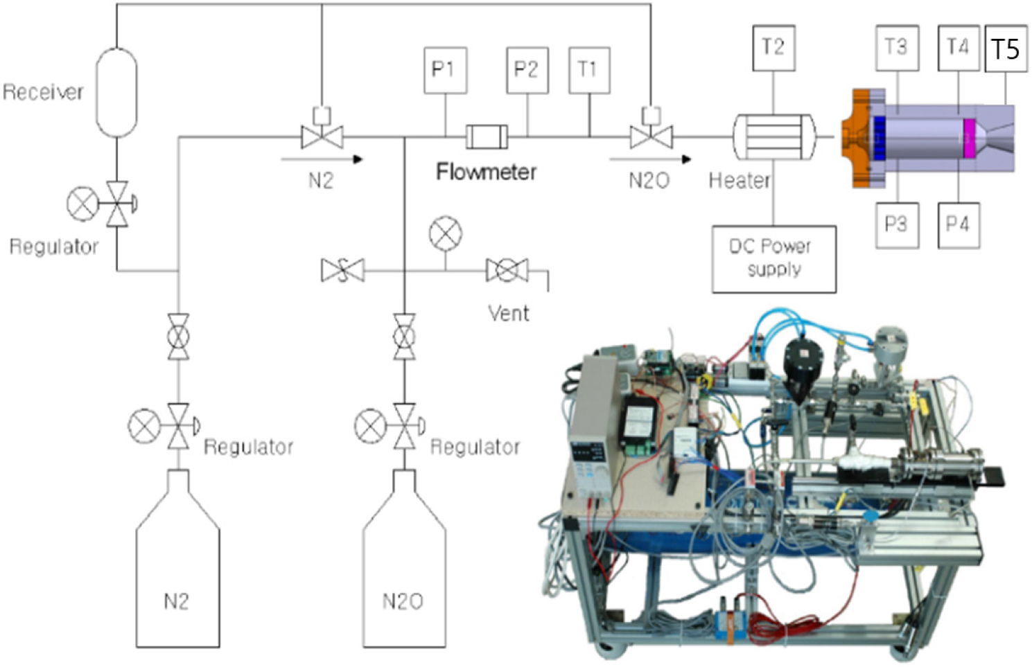
The test facility for evaluating N2O monopropellant thruster is shown in Fig. 3. The facility contains a N2O tank, tank pressure regulator, feed line thermocouple, pneumatic valves, turbine flow meter, and electric preheater. The N2O gas was supplied using a pneumatic valve on the remote site, and the N2O flow rate was regulated with a sonic orifice. The preheater was installed in the thruster inlet in order to initiate the N2O decomposition. Both the reactor and the thruster were preheated for a sufficient duration to ensure thermal equilibrium with the catalyst. Considering the difference in heat capacity between the reactor and the thruster, the reactor was preheated for 1 minute, while the thruster was preheated for 3 minutes.
The N2O mass flow rate was calculated by measuring the volumetric flow rate, temperature (Ts), and pressure (Ps) at the thruster inlet. Calculation results were in good agreement with 1-D isentropic flow equation given by Eq. (3).
where , γ, At, and R denote the N2O mass flow rate, specific heat ratio, throat area of the thruster nozzle, and the gas constant, respectively.
3. Results and Discussion
3.1 Characterization of the Catalyst
The γ-Al2O3 pellet with the surface area of 220 m2/g was used as the catalyst support. However, the surface area sharply decreased at temperature higher than 1000°C. The γ-phase was then transformed though β-phase to α-phase. Thus, the phase transformation at the high temperature should be prevented in order to maintain the surface area and catalytic activity. Fig. 4(a) shows XRD patterns of the prepared catalysts. In Al2O3 pattern, distinct peaks were observed. This indicates that Al2O3 changed from γ-phase to α-phase. The α-Al2O3 was formed by phase transformation at high temperature. High-intensity peak indicates large particle size; thus, the α-Al2O3 surface area was very small. The Si-Al2O3 heated at 1200°C shows the result that is different from α-Al2O3 pattern. The Si-Al2O3 pattern was similar with γ-Al2O3 one. Thus, Si addition suppresses phase transformation of γ-Al2O3 at high temperature. When Si was loaded into γ-Al2O3 pellet, Si particles penetrated into Al2O3 lattice. Si particles hindered Al2O3 phase transformation at high temperature; thus, Si-Al2O3 maintained γ-phase at 1200°C. Ru/Si-Al2O3 and Ru-Si-Al2O3 contain Ru catalyst particles; however, Ru peaks were not observed in XRD patterns. Ru particles were loaded in γ-Al2O3 pores that have a large surface area. Consequently, Ru particles become dispersed over γ-Al2O3 surface. Therefore, the peak intensity was very low. We found that Ru/Si-Al2O3 and Ru-Si-Al2O3 catalysts sustained a large surface area at high temperature.
Fig. 4(b) shows SEM images of the prepared catalysts. The prepared catalysts had different surface structures from a bare γ-Al2O3. Al2O3 heated at 1200°C had α-Al2O3 surface morphology. α-Al2O3 contained distinct particles larger than γ-Al2O3 because the particles were aggregated at high temperature. Consequently, the surface area was very small. This agrees with XRD results that Al2O3 phase was transformed from γ-phase to α-phase at the high temperature. The Si-Al2O3 shows a surface structure similar to that of the bare γ-Al2O3; thus, Si addition decreases particle aggregation at high temperature. Consequently, Si-Al2O3 maintained γ-Al2O3 phase; thus, it provided large surface area.
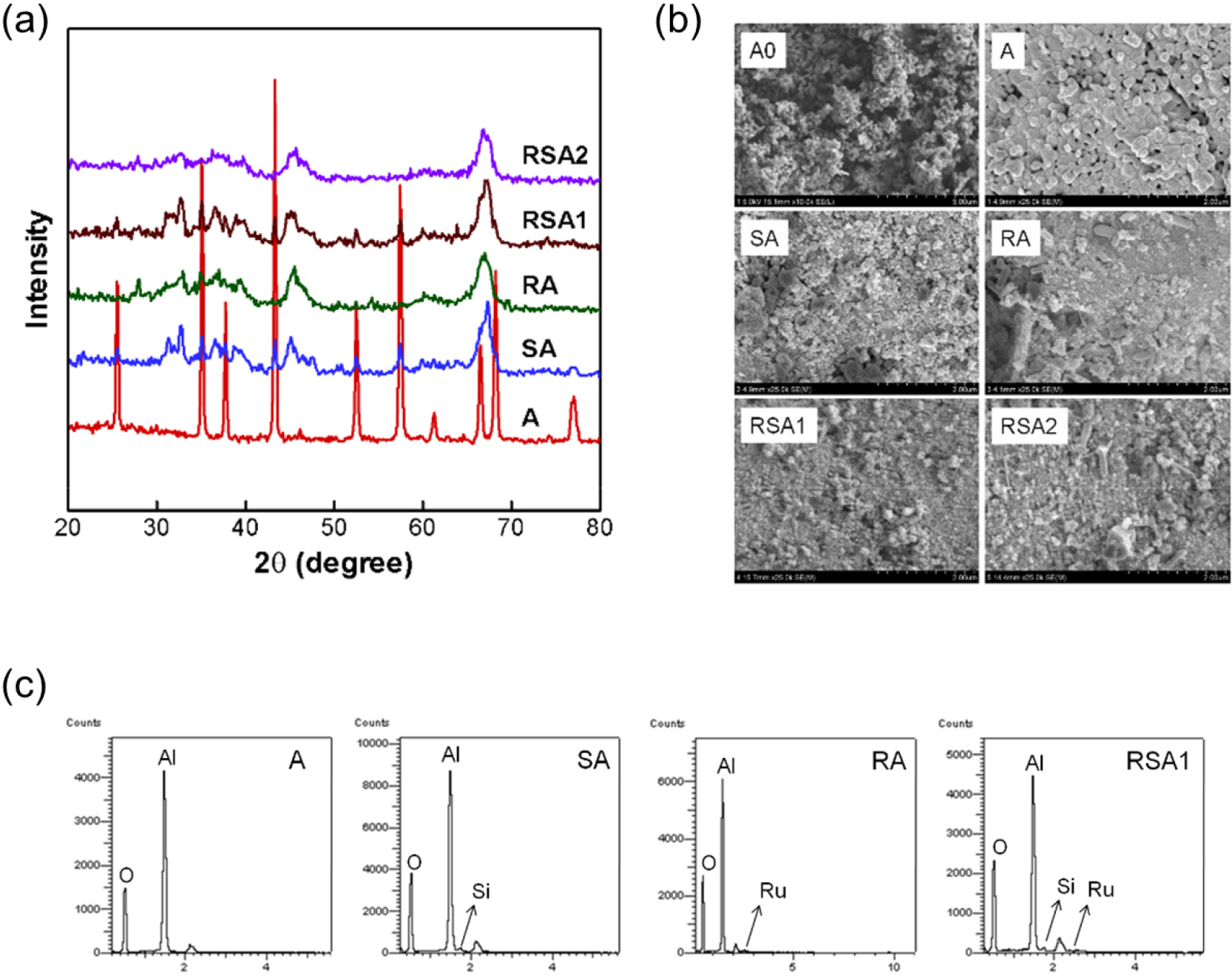
Fig. 4(b) shows SEM images of the prepared catalysts. The prepared catalysts had different surface structures from a bare γ-Al2O3. Al2O3 heated at 1200°C had α-Al2O3 surface morphology. α-Al2O3 contained distinct particles larger than γ-Al2O3 because the particles were aggregated at high temperature. Consequently, the surface area was very small. This agrees with XRD results that Al2O3 phase was transformed from γ-phase to α-phase at the high temperature. The Si-Al2O3 shows a surface structure similar to that of the bare γ-Al2O3; thus, Si addition decreases particle aggregation at high temperature. Consequently, Si-Al2O3 maintained γ-Al2O3 phase; thus, it provided large surface area.
Different surface morphology was observed in Ru/Si-Al2O3 and Ru-Si-Al2O3 catalysts. Both catalysts contain the same elements such as Ru and Si, while their preparation method is different. The Ru-Si-Al2O3 catalyst was prepared by simultaneously loading Ru and Si in the Al2O3. Large Ru particles were observed on the Al2O3 surface indicating that Ru particles are not well dispersed in Al2O3 pores. The Ru/Si-Al2O3 catalyst was prepared by loading Ru in Si-Al2O3. Large Ru particles were not seen in the SEM image; that is Ru/Si-Al2O3 catalyst has higher Ru loadings and higher surface area than Ru-Si-Al2O3 catalyst. Fig. 4(c) shows EDS analysis of the prepared catalysts. In the EDS result of Si-Al2O3, Si presence was identified. Si to Al2O3 ratio was measured as 5.0. Ru/Al2O3 and Ru/Si-Al2O3 results identified Ru presence that was not observed in XRD patterns. These results show that Ru and Si were properly loaded into Al2O3.
3.2 Reactivity of catalysts at N2O decomposition
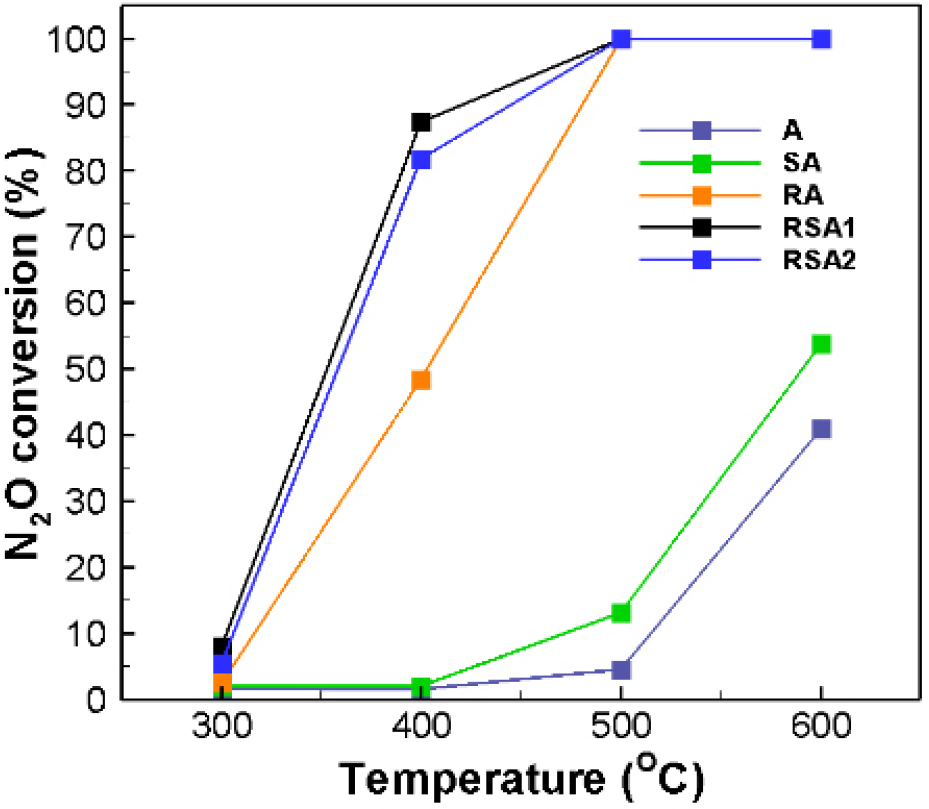
Fig. 5 shows N2O conversion on the prepared catalysts depending on reaction temperature. Al2O3 and Si-Al2O3 had low conversion throughout the entire range because Ru catalyst was not loaded. Si-Al2O3 had higher N2O conversion than Al2O3 at 500°C; that is Si had reactivity at N2O decomposition. The results of comparison of Ru/Al2O3 and Ru/Si-Al2O3 show the effect of Si addition to N2O conversion. In both catalysts, N2O conversion increased with the reaction temperature and 100% conversion was obtained at temperature higher than 500°C. At temperature lower than 500°C, however, the results were different; Ru/Si-Al2O3 catalyst had 87.3% conversion, while Ru/Al2O3 catalyst had only 48.5% conversion at 400°C. This indicates that Si addition increases N2O conversion at low temperature. Both Ru/Si-Al2O3 and Ru-Si-Al2O3 catalysts show 100% conversion at temperature higher than 500°C. At 400°C, however, Ru/Si-Al2O3 catalyst had N2O conversion slightly higher than Ru-Si-Al2O3 catalyst. The N2O conversion was improved due to good Ru dispersion of Ru/Si-Al2O3 catalyst as shown in SEM images of Fig. 4(b).
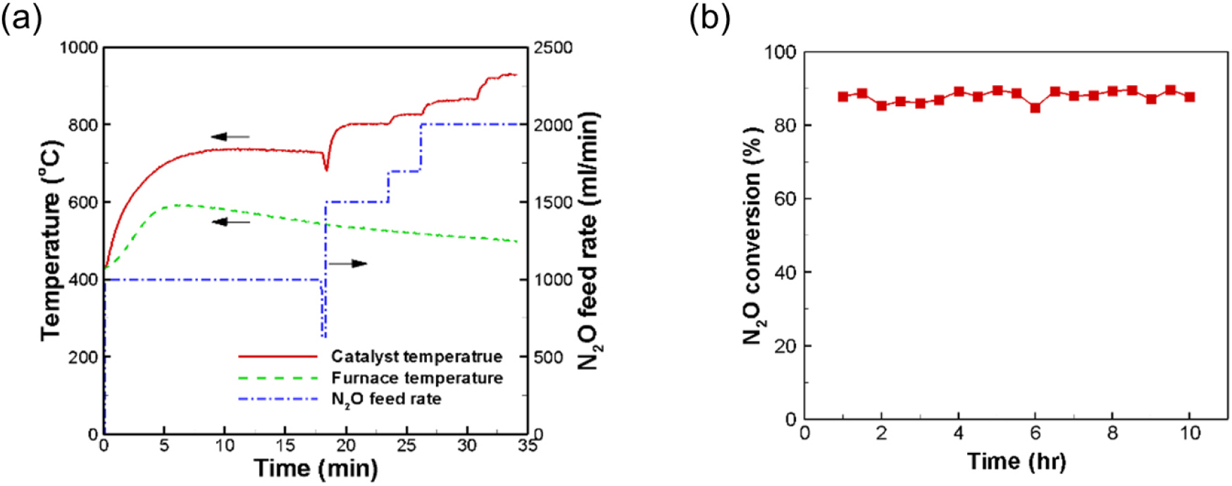
Self-sustained N2O decomposition on the Ru/Si-Al2O3 catalyst was performed as shown in Fig. 6(a). The preheating temperature was 420°C and the N2O feed rate varied from 1000 to 2000 ml/min. The temperature rapidly increased after N2O was supplied. Subsequently, the temperature reached a steady value and was maintained at 735°C. The temperature, however, varied greatly with N2O feed rate. The maximum registered temperature was 930°C at N2O feed rate of 2000 ml/min. At that time, product gases included 28.7% O2, 58.51% N2, and 12.8% N2O; thus, N2O conversion was 87.2%. N2O decomposition was continued for 10 hours in order to evaluate the catalyst durability. N2O conversion was maintained for 10 hours as shown in Fig. 6(b).
3.3 Hot-fire test of N2O monopropellant thruster
Fig. 7(a) shows the N2O mass flow rate and supply pressure of the monopropellant thruster. The supply pressure ranges from 5.5 to 11 bar. The maximum N2O flow rate was 1.93 g/s at 11 bar. Temperature distribution in the thruster is shown in Fig. 7(b). The temperatures at the rear part of the thruster (T3 and T4) sharply increased within 3 min after N2O was supplied, reaching 1120°C. Exit temperature (T5) increased with time, while T2-T4 temperature goes down. While the internal temperature of the thruster tended to rise with increasing mass flow rate, a consistent trend was not observed. This phenomenon is presumed to result from non-uniform heat transfer within the thruster, caused by the localized decomposition of N2O as it passes through the catalyst bed.
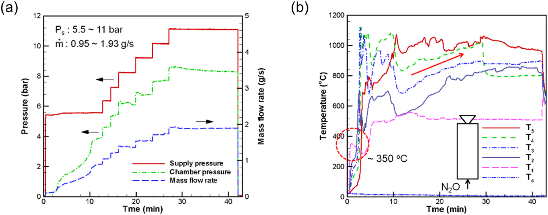
The N2O feed rate gradually increased 11 min after the startup. T2-T4 temperature then increased, while T5 remained constant. At the maximum N2O feed rate of 1.93 g/s, the exit temperature and chamber pressure were 1063°C and 9.32 bar, respectively. The c*-efficiency was used to express the degree of the propellant decomposition as Eq. (4).
where, c*, Pc, At, , γ, R, and Tc denote the characteristic velocity, chamber pressure, throat area of the thruster nozzle, N2O mass flow rate, specific heat ratio, gas constant, and the chamber temperature, respectively. The c*-efficiency was calculated with the above measured pressure, temperature, and mass flow rate. The c*-efficiency was 89.05% at 1063°C and 9.32 bar. The hot-fire tests validated that Ru/Si-Al2O3 catalyst is feasible for N2O decomposition for a monopropellant thruster.
4. Conclusion
Heat-resistive Ru catalyst supported on Si-doped Al2O3 for N2O monopropellant decomposition was prepared. The γ-Al2O3 was not transformed into α-Al2O3 by adding Si element to Al2O3 support. It was shown that the amorphous Si-Al2O3 was obtained at 1200°C using SEM/EDS and XRD analysis. Ru/Si-Al2O3 had better Ru dispersion in Al2O3 support. Ru/Si-Al2O3 has the highest conversion on N2O decomposition. N2O decomposition on Ru/Si-Al2O3 was self-sustained and did not require additional heat supply. The hot-fire tests of the subscale N2O monopropellant thruster containing the Ru/Si-Al2O3 catalyst were conducted, resulting in high c*-efficiency as 89.05%.
