

1. Introduction
2. Numerical Analysis
2.1 Nozzle Design
2.2 CFD Model
2.3 Numerical Results
3. Fabrication and Experimental Verification
3.1 Fabrication and Dimensional Characterization
3.2 Thrust Measurement
3.3 Comparison with Numerical Results
4. Conclusion
1. Introduction
The number of launches and applications of nanosatellites and other small satellites has been steadily increasing. Major spacefaring nations operate such spacecraft in formation or as constellations for a wide range of missions, including Earth observation, ocean monitoring, scientific tasks, and military applications [1,2]. To support formation flying and mission operations, propulsion capabilities are required for orbital maneuvers and attitude control, typically ranging from tens of micronewtons to hundreds of millinewtons. Accordingly, various propulsion systems have been investigated for small satellites, including cold-gas thrusters, monopropellant thrusters, bipropellant thrusters, solid propellant thrusters, and electric propulsion systems [3,4,5].
Among these options, cold-gas thrusters offer a relatively simple architecture, are straightforward to fabricate and characterize in thrust testing, and can be implemented reliably using MEMS (Microelectromechanical Systems) processes [5,6]. In cold-gas thrusters, the micronozzle is a key component responsible for generating thrust. DRIE (Deep Reactive Ion Etching) is a representative method for fabricating micronozzles [7,8]. DRIE is widely used in MEMS processing and provides a practical route to producing high-aspect-ratio microstructures. In particular, the Bosch DRIE process alternates etch and sidewall passivation steps, enabling high etch rates and high-aspect-ratio features. This process consists of a cycle in which SF₆-based etching and C₄F₈-based passivation are alternately performed. During the etching step, silicon is removed, whereas in the passivation step, a protective layer is formed on the sidewalls, resulting in anisotropic etching in the vertical direction. However, due to the repetitive nature of the process, stepwise etching occurs in each cycle, leading to the formation of periodic surface undulations, known as scallops, on the sidewalls [8]. The size and shape of these scallops are determined by process parameters such as cycle time, RF power, gas flow rate, and chamber pressure. These fabrication-induced surface features can influence boundary layer development and flow separation behavior, potentially leading to a degradation in nozzle thrust performance [9,10]. Therefore, for Bosch-DRIE-fabricated micronozzles to be applied in practical propulsion systems, accurate prediction of microscale internal flows and quantitative evaluation of fabrication-induced geometric imperfections are required.
In previous studies, Bayt et al. [7,11] conducted two-dimensional numerical simulations of micro supersonic nozzles and reported that wall slip boundary conditions did not lead to a significant change in performance for throat diameters on the order of several tens of micrometers. They also showed that boundary layer growth becomes more pronounced at low Reynolds numbers, reducing the effective flow area and thereby decreasing mass flow rate and thrust efficiency. Furthermore, they fabricated two-dimensional micronozzles using DRIE and performed mass flow and thrust measurements, confirming performance degradation trends under low-Reynolds-number conditions. Cai et al. [12,13] numerically investigated friction losses associated with surface roughness in microscale C-D (Converging-Diverging) nozzles and found that increasing roughness reduces thrust efficiency and the effective area ratio; these trends were validated experimentally using a nozzle with a 1 mm throat diameter.
However, quantitative assessments of Bosch-DRIE-induced geometric imperfections in three-dimensional, axisymmetric nozzles remain limited. In this study, axisymmetric micronozzles fabricated using a Bosch-based DRIE process are investigated, and the influence of Bosch-induced scalloping on thrust performance is quantitatively assessed. CFD (Computational Fluid Dynamics) simulations are performed to analyze internal flow characteristics and geometric sensitivity, and thrust measurements of the fabricated nozzles are conducted to validate the numerical results.
2. Numerical Analysis
2.1 Nozzle Design
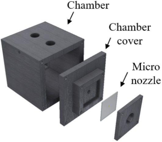
The thrust range of micro-propulsion systems applied to small satellites varies depending on mission requirements and satellite size, and is generally reported to be on the order of tens of µN to several hundred mN [14,15,16,17]. For example, commercially available cold gas thrusters developed by Moog typically operate in the range of a few mN up to approximately 120 mN. Accordingly, in this study, thrust levels of 50 mN and 100 mN under atmospheric conditions were selected as representative intermediate-scale thrust conditions within this range. A hole-type nozzle geometry was selected considering the characteristics of the DRIE process and fabrication cost. A schematic of the proposed micro cold gas thruster is shown in Fig. 1. The operating pressure and temperature were 10 bar and 300 K, respectively, and nitrogen was used as the working fluid. The nozzle was designed based on one-dimensional isentropic-flow relations, and the ideal-gas equation of state was employed to determine the mass flow rate and exit velocity. The resulting throat diameters corresponding to the target thrust levels were 250 µm and 350 µm, respectively.
2.2 CFD Model
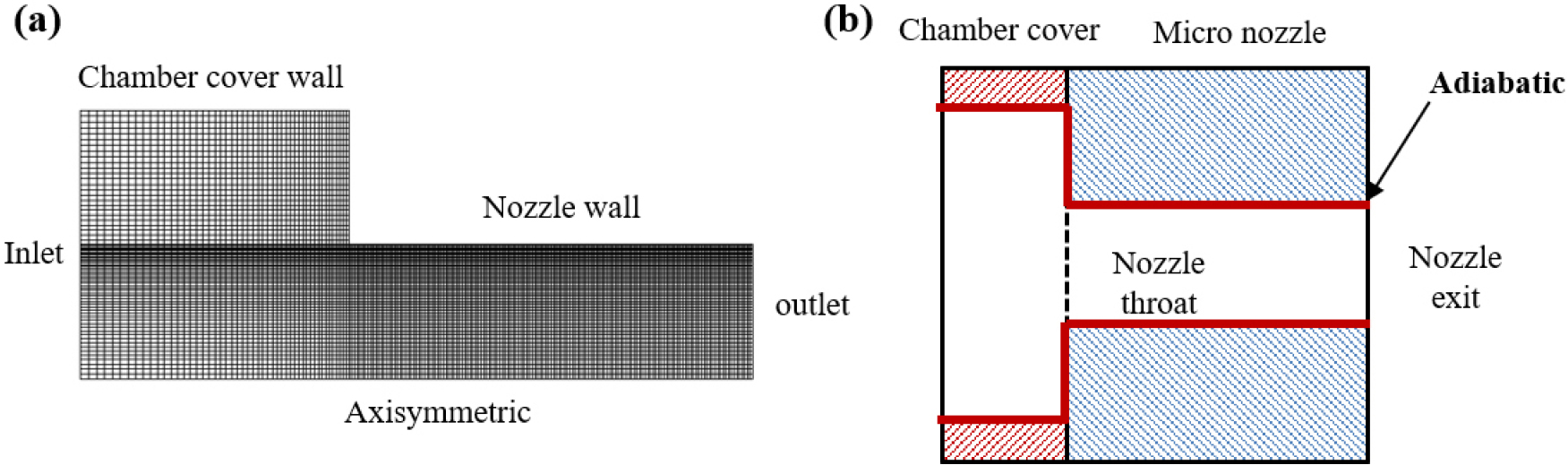
Steady-state CFD simulations were performed to evaluate the performance of the hole-type nozzle. The mesh was refined near the nozzle wall to satisfy , and approximately 11,250 cells were used. Simulations were conducted using the commercial solver ANSYS Fluent. An adiabatic wall boundary condition was applied to neglect heat transfer through the wall, and viscous effects were considered. For computational efficiency, a two-dimensional axisymmetric model was adopted. The ambient condition was set to 1 atm and 300 K. Pressure-inlet and pressure-outlet boundary conditions were applied at the nozzle inlet and outlet, respectively. The computational grid and boundary conditions of the micro nozzle are illustrated in Fig. 2. The governing equations solved for the micronozzle flow are the conservation equations of mass, momentum, and energy, written as follows.
In general, the turbulence model is commonly used with wall functions, which typically require . However, because near-wall flow features are important in micronozzles, the present study employed a fine near-wall mesh satisfying . Accordingly, the SST (Shear-Stress-Transport) turbulence model was adopted for improved near-wall prediction. Scallops generated during the DRIE process can be represented either by directly modeling the geometry or by employing a wall roughness condition. However, explicitly modeling the scallop geometry significantly increases the number of computational cells. Therefore, to reduce computational cost, a wall roughness condition was applied. To determine the equivalent wall roughness height, the scallop height of the fabricated micronozzle was measured using a FIB-SEM (Focused Ion Beam-Scanning Electron Microscope). For the nozzle with a throat diameter of 250 µm, the scallop height was approximately 0.6 µm. This value was used as the equivalent wall roughness height in the CFD simulations. The roughness constant was set to 0.5, and steady-state simulations were performed.
2.3 Numerical Results
Fig. 3(a) shows the Mach number distributions obtained from the CFD simulations for different nozzle throat diameters, illustrating the effect of nozzle scale on the flow field. Fig. 3(b) compares the thrust performance for various nozzle throat diameters and equivalent wall roughness conditions representing DRIE-induced scalloping. The x-axis represents the surface roughness parameter 𝛿, defined as the ratio of the equivalent roughness height to the nozzle throat radius .
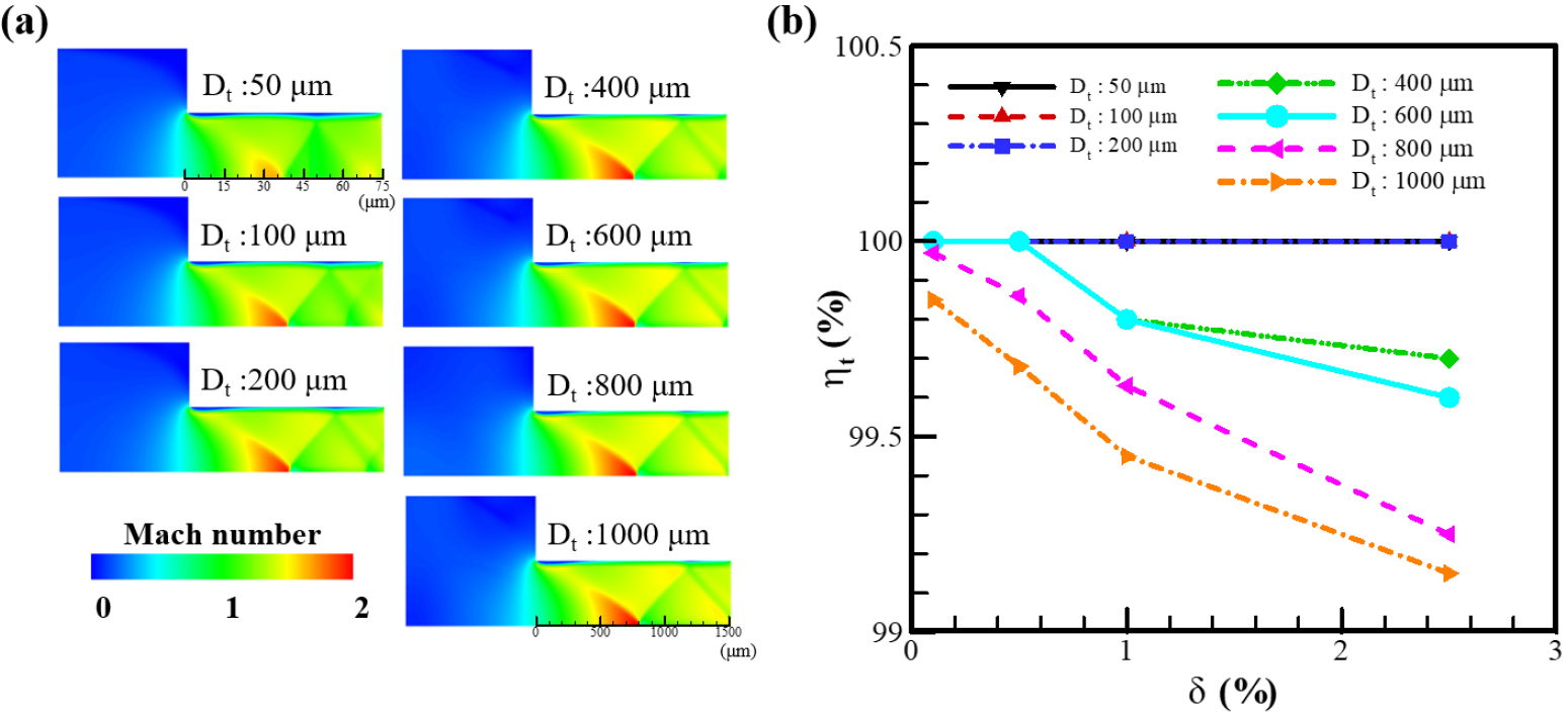
The y-axis represents the thrust ratio , defined as the ratio of thrust predicted with roughness to that without roughness.
As 𝛿 increased, the thrust performance decreased. This trend is likely attributable to increased near-wall losses associated with higher wall roughness, which enhances boundary layer effects and reduces effective flow performance. Notably, the thrust reduction due to roughness became less pronounced as the nozzle size decreased. For throat diameters below 200 µm, the effect of roughness on thrust was very small, whereas for throat diameters of 400 µm and above, thrust decreased as the roughness level increased. This behavior indicates that thrust sensitivity to surface roughness decreases as the nozzle size is reduced under the present operating conditions, resulting in a smaller perturbation to the internal flow field. For a nozzle with a throat diameter of 400 µm, the thrust variation remained within 1% for relative roughness values of 𝛿 ≤ 2.0%. Since the target throat diameters in the present study are 250 µm and 350 µm, the absolute scallop height corresponds to a comparable or smaller relative roughness level. Therefore, the effect of DRIE-induced scalloping, represented here by equivalent wall roughness, is expected to be negligible under the present design conditions.
3. Fabrication and Experimental Verification
3.1 Fabrication and Dimensional Characterization
The micronozzles were fabricated on 8-inch silicon wafers using a Bosch-based DRIE process. Etching was performed using a Deep Si etcher (STS, VPX Pegasus), and the overall process flow and key parameters are summarized in Fig. 4 and Table 1. The wafer thickness was adjusted to 400 µm by CMP (Chemical-Mechanical Polishing). A backside protective layer was then formed, and a 20 µm-thick negative photoresist was patterned. Subsequently, Bosch DRIE was applied by alternating etch and sidewall passivation steps to form axisymmetric hole-type nozzles with throat diameters of 250 µm and 350 µm.
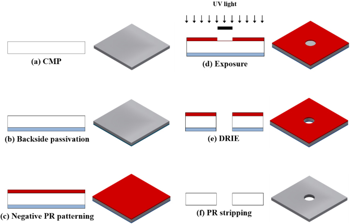
Table 1.
Process recipe for hole-type nozzle fabrication.
| Process step | Time (s) | Pressure (mTorr) | Gas | Flow rate (sccm) | Source power (W) |
| Passivation | 3 | 25 | C4F8 | 200 | 2000 |
| Etch | 9 | 60 | SF6 | 250 | 3000 |
| O2 | 20 | 40 |
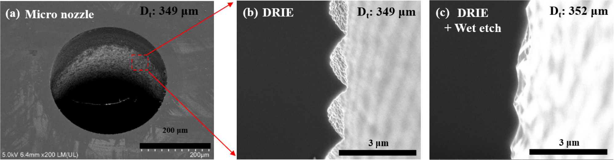
The fabricated nozzles were characterized using an ultra-high-resolution field-emission scanning electron microscope (UHR FE-SEM; SU8230) and a dual-beam FIB-SEM system to measure the throat diameter and cross-sectional geometry. The measured throat diameters were 249 µm and 349 µm, respectively. The nozzles were slightly smaller than the design values, which may be attributed to fabrication and measurement uncertainties. The average scallop heights for the nozzles designed with throat diameters of 250 µm and 350 µm were 0.6 µm and 0.7 µm, respectively, corresponding to 𝛿 ≈ 0.4-0.5%. Based on the numerical results, this level of scalloping is not expected to cause a significant degradation in thrust performance. Nevertheless, to examine the effect experimentally, scalloping was removed by wet etching. Specifically, the micronozzles were immersed in a KOH solution at 70°C to smooth the scalloped sidewalls. Fig. 5 presents SEM images of the fabricated hole-type nozzle with a 350 µm design throat diameter, including the as-fabricated condition (a), the DRIE-induced scallop structure (b), and the surface after wet etching (c). After wet etching, the measured throat diameters increased to 251 µm and 352 µm for the 250 µm and 350 µm designs, respectively. This increase is primarily due to isotropic wet etching, in addition to fabrication and measurement uncertainties
3.2 Thrust Measurement
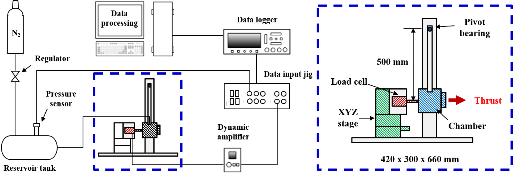
Fig. 6 shows a schematic of the thrust measurement setup. A pendulum-type thrust stand with a pivot bearing was employed. The pendulum length was 500 mm, and the overall stand dimensions were 420 × 360 × 600 mm. A cubic chamber with a side length of 50 mm was used, and the micronozzle was mounted to the chamber via a lid. Thrust was measured using a load cell (KYOWA, LTS-50GA; full-scale capacity: 500 mN). The load cell has an overall accuracy of approximately ±0.5% RO, based on the manufacturer’s specifications for nonlinearity, hysteresis, and repeatability. A contact hole was machined on the rear side of the chamber, and the load cell and chamber were aligned using a precision XYZ stage (TOS, LDV-LM-C2; resolution: 0.01 mm) prior to testing.
To validate the CFD results and evaluate nozzle performance, thrust was measured for nozzles with scalloping (as-fabricated) and for nozzles after scallop removal (wet-etched). Tests were conducted over an operating pressure range of 4-10 bar for the nozzles designed with throat diameters of 250 µm and 350 µm, as well as for the corresponding wet-etched nozzles.
3.3 Comparison with Numerical Results
Fig. 7 and Table 2 compare the CFD predictions and experimentally measured thrust values for each nozzle throat diameter. Due to pressure control fluctuations, the experiments were conducted within approximately 9.9-10.3 bar. For consistent comparison, the thrust at 10 bar was obtained by curve fitting of the measured data. The maximum difference between the CFD and experimental thrust values was 3.5%, which may be attributed to numerical uncertainties and experimental errors such as instrumentation, alignment, and pressure control.
When comparing the thrust of the as-fabricated nozzle with scalloping and the wet-etched nozzle without scalloping, the CFD and experimental results exhibited consistent trends. The observed thrust difference is more plausibly associated with the increase in throat diameter (approximately 0.8-0.9%) caused by wet etching rather than with the presence of scalloping itself. Because the throat diameter directly affects the mass flow rate, even a small diameter change can lead to a measurable change in thrust. In contrast, the measured relative scallop size (𝛿 ≤ 0.5%) is expected to have a limited impact on additional flow losses, consistent with the numerical results. These results suggest that, under the conditions considered, Bosch-DRIE-induced scalloping has a negligible effect on thrust performance.
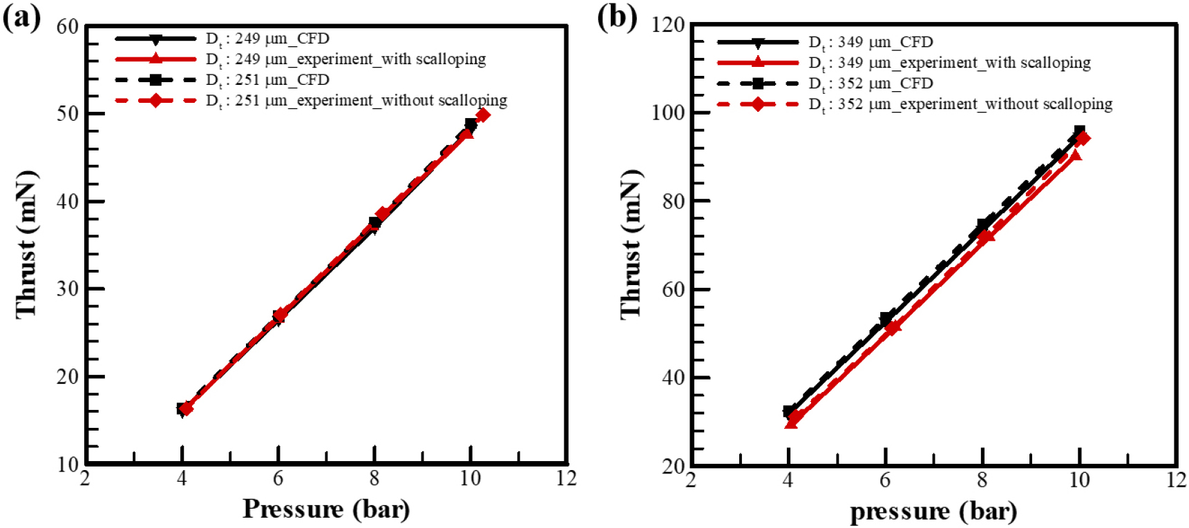
Table 2.
Comparison of thrust at 10 bar.
4. Conclusion
In this study, the influence of Bosch-DRIE-induced scalloping on the thrust performance of axisymmetric micronozzles fabricated by DRIE was investigated through numerical analysis and experiments. Numerical results for various throat diameters and scallop (equivalent roughness) conditions indicated that, for throat diameters up to 400 µm, the thrust variation remained within 1% when the relative roughness parameter 𝛿 was below 2%. Experimentally, the effect of geometric modification was examined by comparing thrust before and after scallop removal. The measured thrust difference was found to be more closely related to the increase in throat diameter introduced during wet etching than to the removal of scalloping itself, implying that cross-sectional area variations are a dominant factor governing thrust sensitivity in micronozzles. Therefore, under the conditions considered, Bosch-DRIE-induced scalloping lies within a range where its impact on thrust is not significant. The findings provide practical guidance for setting fabrication tolerances in the design of MEMS-based cold gas micronozzles.
