

1. Introduction
2. Modeling approaches
2.1 Closed loop analysis
2.2 Thermo-acoustic model
2.3 Flame dynamical model
3. Analysis
3.1 Model Analysis
3.2 Model Conditions
4. Results
4.1 Flame image analysis to derive time delay values.
4.2 Model validation
4.3 Influence of mean flow on instability characteristics
4.4 Parameter study on combustion instability
5. Conclusions
Nomenclature
: Velocity
: Density
: Reflection coefficient
: Riemann invariants
: Speed of sound
: Specific heat in constant volume
: Specific Heat in constant pressure
: Ratio of specific heats
: Duct area
: Area ratio (i=1,2)
: Mach number
: One-way period of wave propagation
s : Complex Laplace variable
: Heat release rate
: Round-trip period of wave propagation
Superscripts
: Downstream direction
: Upstream direction
Subscripts
k=1,2,3 : Duct index
j=1,2 : Steady temperature index
Overscripts
□' : Perturbation value
: Mean value
1. Introduction
Combustion instability (CI) occurs due to interaction of acoustic oscillations and unsteady heat release perturbations. This phenomenon has been extensively studied, and researchers have identified that acoustic characteristics of a combustion system plays a crucial role [1,2]. According to the reference [3], the Rayleigh criterion “spontaneous excitation of acoustic oscillations within a combustor can only occur when energy supply rate from periodic combustion process to acoustic field surpasses rate at which acoustic energy is dissipated within combustor or transmitted through its boundaries.” can be written as
where , , T, V, and denote the heat input fluctuations, unsteady pressure fluctuation, the period of oscillations, combustor volume, and i-th acoustic energy loss function.
Correct anticipation of CI prior to its occurrence is of paramount importance. There are different approaches for analyzing CI. Analytic approach based on a simple one-dimensional acoustic model. First approach involves with a simple analytic thermoacoustic combustor model and a flame dynamical model, and CI is determined from the stability of a closed loop system characterized by the two models [4,5]. Another approach is a numerical one such as the Large Eddy Simulation (LES) in which the coupled dynamics of flame and acoustics are simultaneously solved [6,7].
Compared to numerical approaches, a significant merit of the analytic approach is that it allows us to make parametric study in an analytic way. In contrast, expensive numerical computations are generally required repetitively in numerical approaches. This is why an analytic approach is adopted in this paper.
There are a lot of 1-D acoustic models in literature [1,4,5,8,9] and many of them are based on the zero mean flow assumptions. Although the effects of mean flow on thermo-acoustics of combustors and CI have been investigated in the work [4], in this paper, their findings are generalized for a real-world combustor with a premixer, focusing on the quantitative impact of mean flow and flame characteristics on CI.
2. Modeling approaches
The CI is the feedback loop between combustion process and acoustic oscillations within a combustion chamber [1,4]. A control theoretic approach is employed here, utilizing transfer function representations of thermo-acoustic and flame dynamics [4,10]. Our thermo-acoustic model and CI predictions are validated against results from both a commercial finite element method software COMSOL and experiments [11].
2.1 Closed loop analysis
Linear acoustics and combustion dynamics of a combustor at a fixed operating condition can be represented as two interconnected transfer functions shown in Fig. 1[4].
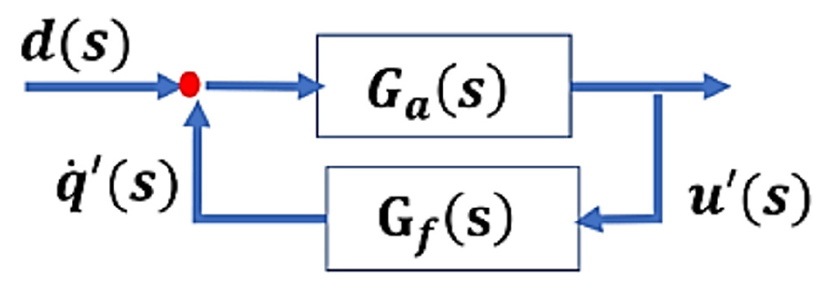
The transfer functions “” and “” in Fig. 1 denote a thermo-acoustic combustor model and a flame dynamical model, respectively. The transfer functions has heat fluctuation input and the resulting velocity perturbation output. The input-output roles of the heat and velocity fluctuations in is completely reversed in the transfer functions . The vice-versa relation is making a closed loop system given
In addition, and in Fig. 1 represent velocity fluctuations and heat release rate perturbations, respectively, and represents an external disturbance.
From control theoretic perspective, CI is a consequence of a feedback configuration of the two transfer functions and , as given in Eq. (2). The roots of the equation are complex-valued in general and CI occurs if and only if the real part of any root has non-negative values.
2.2 Thermo-acoustic model
Our analytic approach represents a combustor system as a network of interconnected acoustic elements, each defined by its acoustic properties and geometric features. Adopting the approaches in the literature [5,9], the complex geometry of a target gas turbine combustor is simplified into a combination of three one-dimensional ducts as illustrated in Fig. 2(a).
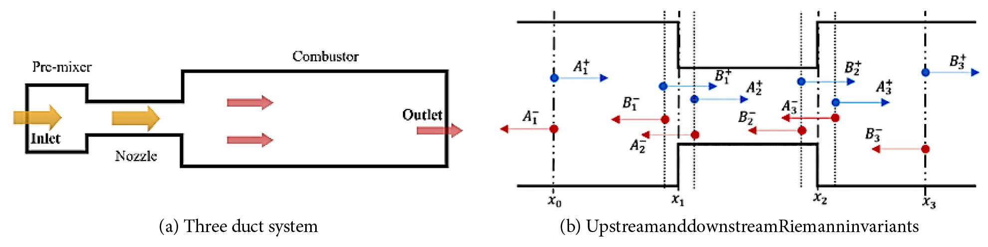
Fig. 2(b) shows upstream and downstream Riemann invariants in each duct, and those invariants are solutions to the Helmholtz equation for one-dimensional uniform ducts.
We define (premixing duct), (nozzle), and (combustion chamber) as cross-sectional areas of three ducts. In addition, for a general temporal-spatial function , we write for the Laplace transform of where denotes the complex variable.
Boundary conditions at the inlet and outlet for the target model are described as reflection coefficients
In each duct, wave propagation is given by
where denotes the time delay
k, and are duct index, sound speed and mean flow velocity, respectively.
Mass and momentum conservation relations are applied from pre-mixer to nozzle at . Assuming no steady heat losses, we have constant temperature and sound speed in both premixer and nozzle, and the relation holds from the adiabatic condition. The velocity and density fluctuations can be represented with Riemann invariants as [5,12],
and the perturbed mass and momentum rate conservation conditions across the point can be written as
equivalently,
where is the area ratio, and is explicitly given in Eq. (9) to come.
From the definition of the reflection coefficient in Eq. (3) and Eq. (6), we obtain
where ,
In the above developments, we have neglected terms of square Mach number assuming a slow mean flow.
To find relations among Riemann invariants at the interface , momentum with and energy conservation relations are applied. Note that, due to the existence of a flame, the relation cannot be used inside a combustion chamber. Instead, we use the mass conservation condition for a representation of density perturbation after the flame given
Similar to the case of the premixer-nozzle interface , at the nozzle-chamber interface , velocity and density fluctuations can be written in terms of the Riemann invariants as
and the momentum and energy conservation relations give
where a, b, d, e, f and g are as
where , , and .
As we have two scalar equations and two unknow quantities and quantities in Eq. (12), for a given input term , can be written in terms of . In addition, from Eq. (5), we have
that is,
An elimination of in Eqs. (12) and (14) gives an explicit form of the thermo-acoustic model
where the numerator and denominator are given
With the parameters
2.3 Flame dynamical model
For current study, flame dynamical model is described as a transfer function from velocity fluctuation to heat rate fluctuation [4], given
However, the flame model popular in literature is defined by the scaled transfer function
And thus it gives our flame transfer function
Here , , , and stand for mean heat release rate, mean flow velocity, gain and time delay, respectively. In addition, the negative sign in Eq. (17) is introduced to consider a positive gain .
3. Analysis
3.1 Model Analysis
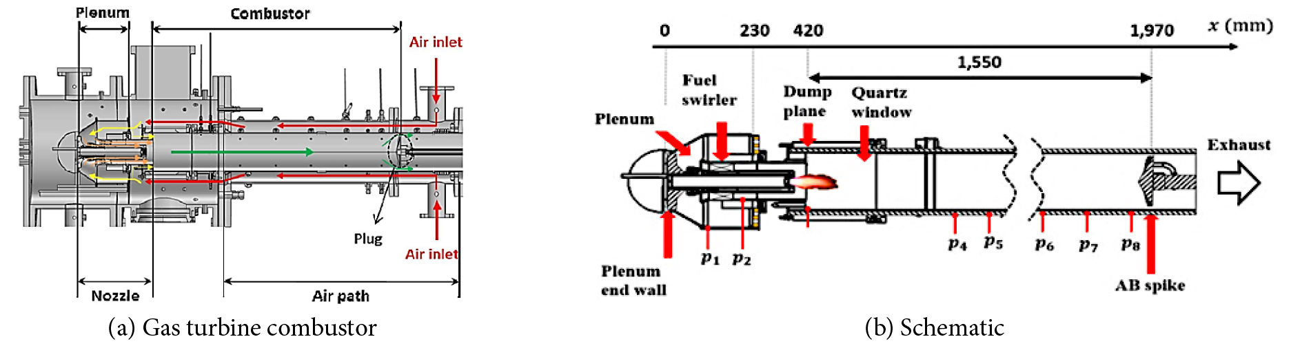
This study considers a single nozzle system for a hydrogen co-firing gas turbine combustor shown in Fig. 3(a), which is currently under development by the Korea Institute of Machinery and Materials (KIMM). The system is composed of an air inlet, air passage, plenum, nozzles, combustion chamber, and a plug. As illustrated in Fig. 3, after entering through the air inlet at the end of the flame chamber, a portion of air flows through the cooling holes of the chamber, while the rest passes through the plenum, fuel nozzles in the plenum toward the flame chamber. Air for combustion is divided to provide a separate supply into the pilot and main nozzles. The burned gas then flows towards the rear end of the combustion chamber and then it is expelled through the plug. A simplified schematic of the KIMM combustor can be found in Fig. 3(b).
The KIMM model in Fig. 2(b) is further simplified to the 3-duct system in Fig. 2(a) for the thermo-acoustic combustor model given by the transfer function in Eq. (15).
3.2 Model Conditions
The inlet temperature, pressure, and air flow rate in Table 2 are measured quantities. Other parameters in Table 1 are derived from the ideal gas law. The subscripts “1” and “2” within the table denote steady physical quantities before and after combustion, assuming adiabatic process in each duct. The proportion of hydrogen in total fuel mixture varies from 0% (i.e., : 100%) to 60%. It is assumed that both the plenum inlet and the combustion chamber outlet are acoustically closed [11]. This assumption is justified since the plug provides a very narrow open area, less than 19% of the cross-sectional chamber area.
4. Results
4.1 Flame image analysis to derive time delay values.
A precise measurement of and of is essential for an accurate analysis of CI. Unfortunately, however, both direct measurements and numerical estimations of those quantities are unavailable at this research stage. To cope with this difficulty, motivated by [13,14], we estimate the parameter as the convective time from a representative heat release location inside flame to the injector location under a steady flow.
The parameter , often called the flame-acoustic interaction strength, has also great impact on CI but this paper will focus on the effect of the delay parameter as done in [9,10,11,12].
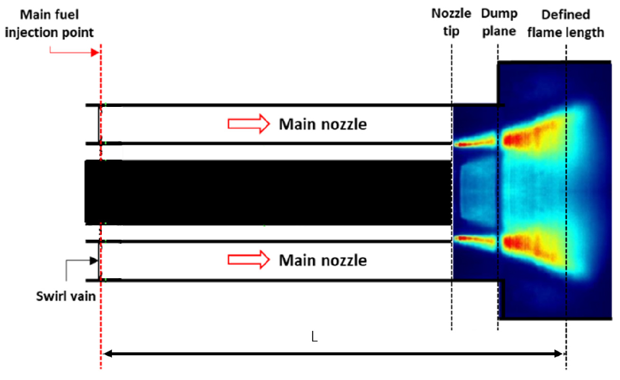
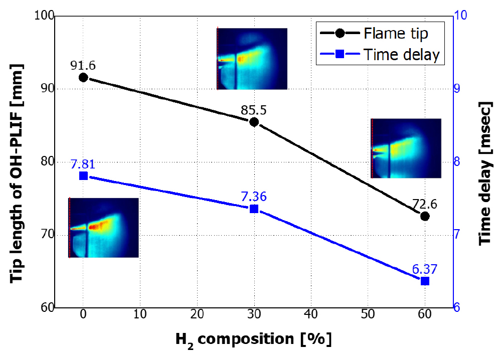
The flame tip, determined by OH-PLIF (planar laser-induced fluorescence) images as shown in Fig. 4, is chosen as representative flame location in this paper.
In general, the OH chemiluminescence during a combustion process can be quantified by using intensified charge-coupled device cameras. In addition, a flame tip of each operational condition can be identified by tracking OH radicals, possibly combined with some image enhancement algorithms [15].
The dependence of time delay on the hydrogen composition is experimentally found as shown in Fig. 5. One can see that time delay parameter decreases as hydrogen composition increases. Specifically, total time delay value varies from 7.81 msec to 6.37 msec for 0% (i.e., : 100%) to 60% hydrogen composition in the total fuel.
4.2 Model validation
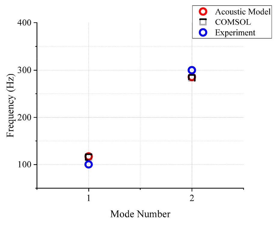
Under zero mean flow and closed-closed boundary condition, the 1st and 2nd resonance frequencies 116.4 Hz and 282.2 Hz could be analytically found from the acoustic transfer function , being the roots of the equation . Those resonance frequencies are verified against the three-dimensional Helmholtz solver in COMSOL (115.6 Hz and 282.5 Hz, respectively) and experimental results (97 Hz and 304 Hz, respectively) with a target combustor operating at 100% methane to the primary fuel source under the conditions outlined in Table 1[10].
A comparison of the resonance frequencies in Fig. 6 suggests the validity of our thermo-acoustic combustor model . Presumably, some discrepancy in Fig. 6 might come from the fact that our thermo-acoustic model and the COMSOL result do not include both the flame dynamics and mean flow present in the experiment.
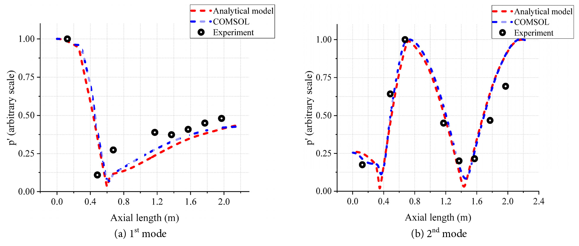
A comparison of pressure mode shapes is made in Fig. 7. The experimental pressure data are obtained at self-excited frequencies, and other mode shapes are associated with the resonance frequencies in Fig. 6. The overall similarity among the mode shapes in Fig. 7 strongly suggests the validity of our thermo-acoustic model. In addition, we can see in Fig. 7 that the first two resonances of our combustor are longitudinal ones.
4.3 Influence of mean flow on instability characteristics
A combination of equations (2), (15), and (19) gives the closed loop combustor given
A significant difference of this model compared to the thermo-acoustic model in Eq. (15) is that it incorporates both the combustor thermo-acoustics and flame dynamics.
The closed loop combustor in Eq. (20) allows us to investigate the impact of mean flow on CI, that is, the growth rate and self-excited frequency, more accurately. A key reason of the expected accuracy is that the self-excited frequency of the experiments is closed-loop resonances, not pure thermo-acoustic resonance of the open loop model in Eq. (15).
Our closed loop study will consider Mach numbers from zero to 0.27, motivated by the fact that the particular Mach number 0.27 is employed in the KIMM experimental conditions. For a case study shown in Fig. 5, the delay parameter ms is chosen which corresponds to 100% methane flame.
The interaction strength parameter in this paper will be a free parameter ranging from 0 to 3. This range was chosen for a lean premixed combustor in the study [11]. However, the particular value of was chosen in this section, for it gives better matching with experimental data.
The roots of the denominator of the closed loop transfer function in Eq. (20), often called the closed loop poles in control engineering depends not only the flame dynamics but also the thermo-acoustic parameters in Eq. (15), being functions of mean flow. As a consequence, mean flow affects growth rates and instability or self-excited frequencies of the closed loop combustor.
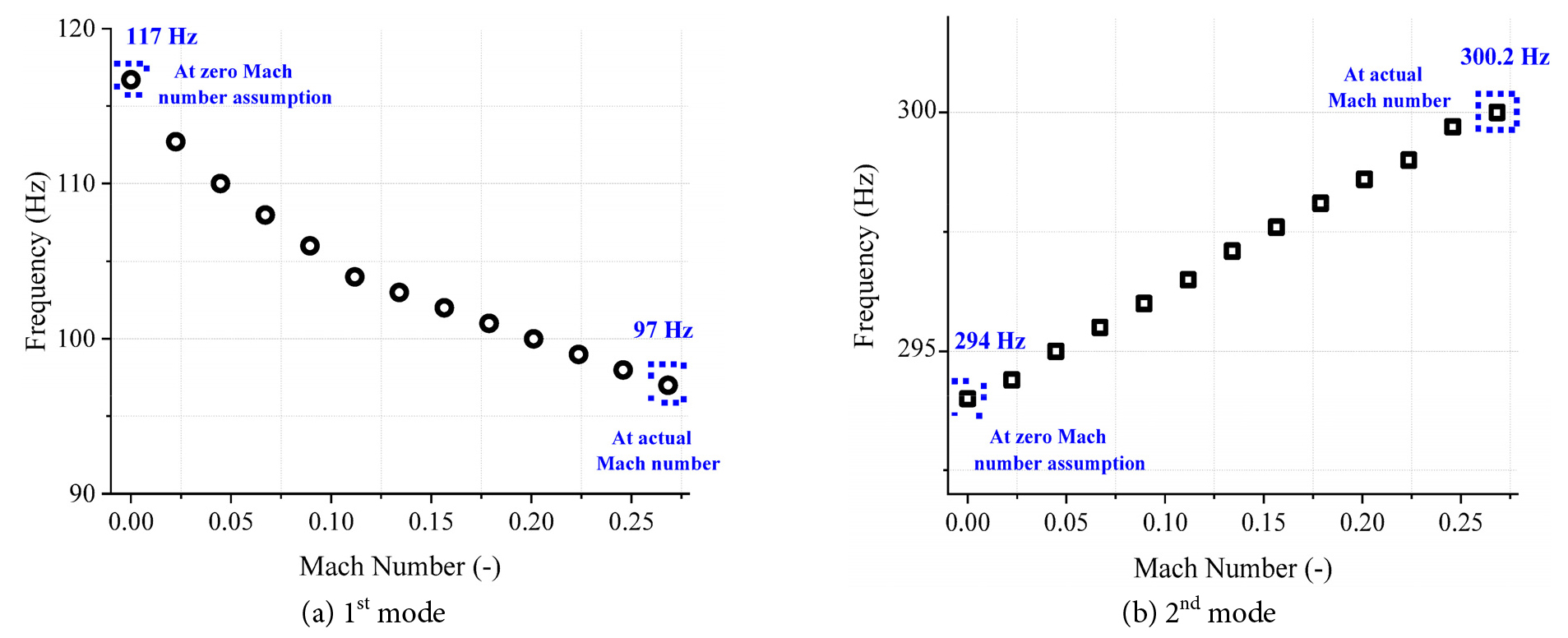
Fig. 8 shows the dependence of self-excited frequency on mean flow. As Mach number increases from 0 to 0.27, the first self-excited frequency changes from 117 Hz to 97 Hz, and the second from 294 Hz to 300.2 Hz. The specific data of the Mach number in Fig. 8 corresponds to the experimental results. We can see that the experimental data 97 Hz and 304 Hz shown in Fig. 6 are surprisingly close to the analytic prediction 97 Hz and 300.2 Hz in Fig. 8.
For an investigation of mean flow effect on growth rate, we first simplify the thermo-acoustic model for the case zero mean flow. In this case, the model in Eq. (15) becomes
where
A comparison of the general case in Eq.(15) and the zero mean flow case in Eq. (21) reveals that the multiplier of the inlet reflection coefficient changes from to , and the outlet reflection coefficient changes from to .
Notice that, as Mach number increase from 0 to 0.27, the parameter decreases from 1 and that increases above 1. In addition, two inequalities and hold for inlet and outlet reflection coefficients. It is found in [4,16] that, if , then the well-known damping effect of mean flow should occur, while an anti-damping effect occurs when .
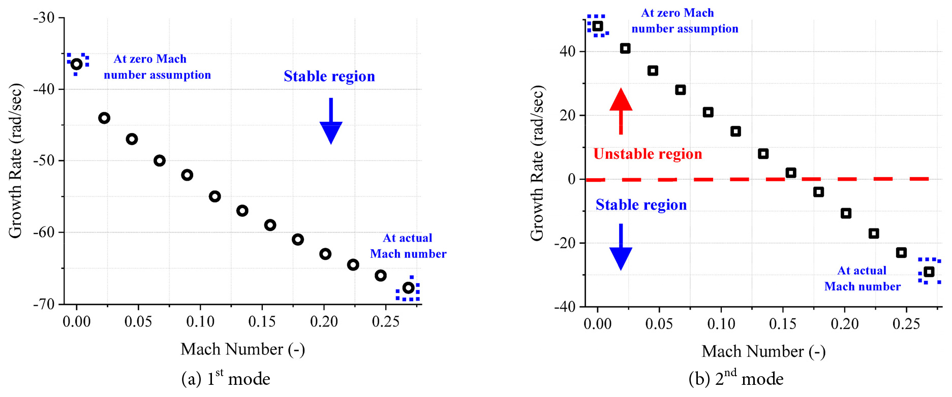
The closed loop combustor model gave the closed loop poles whose real parts (growth rate) are shown in Fig. 9(a) and (b) corresponding to the first and second self-excited frequency, respectively.
We can see that, as Mach number increases from zero to 0.27, the growth rate decreases, indicating the expected damping effect. Another interesting observation in Fig. 9 is that the first mode is always stable for all Mach numbers but the second one is stable only when Mach number is more than 0.17, roughly.
4.4 Parameter study on combustion instability
We have seen in Section 4.1 that the ratio of hydrogen content in the total fuel has an impact on time delay. Motivated by the time delay magnitudes msec of the KIMM’s experimental data (recall Fig. 5), we will assume time delay of 4 to 9 msec in our detailed analysis of hydrogen content impact on CI in this section. In addition, three interaction strength parameters , which is a typical interaction strength for lean premixed combustors [11].
It was found that all poles of the closed loop combustor model in Eq. (20) are significantly affected by the time delay magnitude for every interaction strength parameter. These results are shown in Fig. 10 and Fig. 11 for self-excited frequency and growth rate, respectively. The vertical dashed lines in Figs. 10-11 denote the time delayof the KIMM’s experiments.
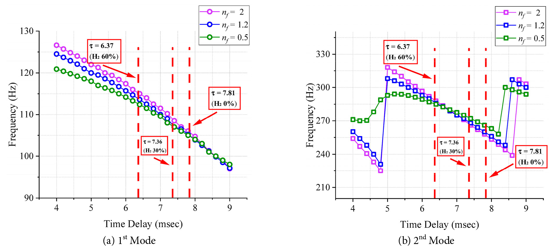
The first two self-excited frequencies of the closed loop combustor system are shown in Fig. 10(a) and (b). An interesting finding is that the first self-excited frequency monotonously decreases, irrespectively of the interaction strength . Interestingly, however, the second frequency has sudden jumps () or an increase () before it monotonously decreases after msec, roughly.
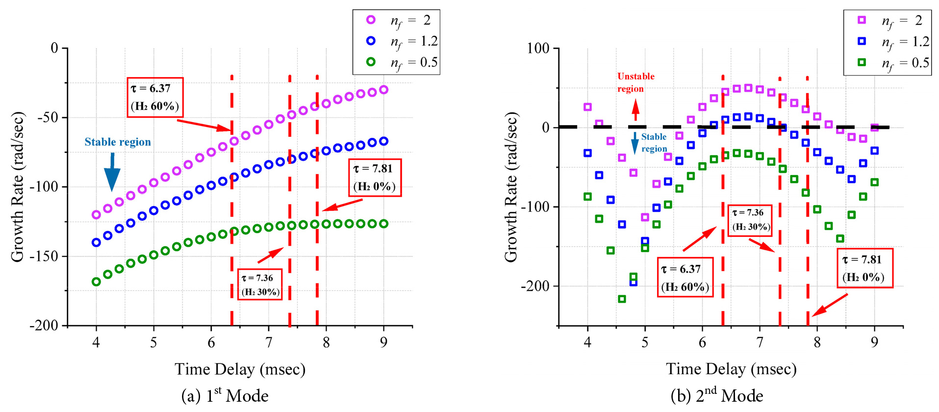
As addressed before, CI does not occur if real parts (growth rate) of the closed loop system are strictly negative. The growth rates associated with the frequencies in Fig. 10 are shown in Fig. 11. It is shown in Fig. 11(a) that the growth rate of the first mode gradually decreases, irrespectively of the interaction strength . A physical implication of this finding is that the first mode will be stable for all hydrogen ratios in total fuel.
However, we can see in Fig. 11(b) that the growth rate variations of the second mode are rather complicated for every interaction strength .
It is noted in Fig. 11(b) that, for every time delay, a stronger interaction increases the growth rate and the combustor system, which is not surprising. In addition, it follows from Fig. 11(b) that, for a fixed interaction strength, growth rate can both increase and decrease as time delay increases. In other words, time delay is a critical parameter for the stability of combustors. From the relation between hydrogen ratio and time delay of the flame dynamics, it follows that the hydrogen ratio significantly influences on the CI.
It is experimentally observed that hydrogen ratio 30-60% makes the KIMM combustor more unstable. This fact suggests that for a given combustor system there exists a certain range of hydrogen ratio with which the combustor becomes more unstable.
5. Conclusions
Our thermo-acoustic based on the network model approach was verified against 3D FEM Helmholtz solver and experiments. Combined with a typical flame dynamical model, we developed a closed loop combustor model. The validity of the closed loop model could be confirmed from a comparison of self-excited frequencies predicted from our model and from experiments.
The effects of mean flow on combustion instability were also investigated and the damping and anti-damping effects could be observed for a closed loop combustor system. In addition, we have noticed that a certain range of hydrogen ratio may cause CI, suggesting the importance of an appropriate hydrogen ratio to avoid possible occurrence of CI.
