

1. Introduction
2. Numerical Method
2.1 Pintle Injector and Combustor Design
2.2 Numerical Modeling
2.3 Grid Independence Test
2.4 Validation
3. Results and Discussion
3.1 Effects of Momentum Ratio
3.2 Effects of Blockage Factor
3.3 Effects of Mixture Ratio
4. Conclusion
1. Introduction
Following the successful landing of the Apollo lunar module on the moon surface in 1969 [1], pintle injectors are receiving renewed attention after their applications in SpaceX’s Falcon 9 and the Chinese lunar lander Chang’E [2,3]. A pintle injector consists of a radial orifice on the side of the pintle and an annular axial orifice around the pintle, which inject oxidizer and fuel, respectively [4]. This unique structure is known to provide controllable propellant injection area, simplicity, and inherent combustion stability. Pintle injectors, originally developed to improve the mixing performance of hypergolic liquid-liquid propellants, are currently also applied to a variety of propellant combinations for gas-liquid injection, such as LOx/H2[5], LOx/CH4[6], and C2H6O/H2O2[7,8].
Most of the 20th century pintle injector research was conducted by TRW [9], and it was reported that the highest combustion efficiency was achieved at an interaction momentum ratio (IMR), which is expressed by Fig. 1 and Eq. (1), around 1 [10,11]. These findings have been repeatedly cited by previous studies as a solid guideline for pintle injector design [12,13] and experimentally reaffirmed by the liquid-liquid pintle injector hot firing tests of Sakaki et al. [14,15].
However, for gas-liquid pintle injectors, some recent works have reported that the peak combustion efficiency was observed at momentum ratios far from 1. Kim et al. experimentally investigated the combustion characteristics of a LOx/GCH4 pintle injector and reported that the combustion efficiency reached its maximum at a momentum ratio of around 0.1 [16]. Vasques et al. reported that the maximum combustion efficiency was achieved at a momentum ratio between 0.1 and 0.2, through hot firing tests of a LOx/GCH4 pintle injector [17]. These results raise questions about TRW’s previous findings and necessitate further exploration into combustion efficiency across a broader range of momentum ratios in gas-liquid pintle injectors, along with other influencing factors.

Therefore, in this study, numerical analysis was conducted over a wide range of momentum ratio to investigate how the combustion efficiency of a gas-liquid pintle injector varies with the momentum ratio. Furthermore, the effects of blockage factor (BF) and mixture ratio (O/F) on the combustion efficiency were also discussed.
2. Numerical Method
2.1 Pintle Injector and Combustor Design
Fig. 2 shows the schematics of a multi-slit type gas-liquid pintle injector used in this study [18]. The injector was designed for a 400 N-class LOx/CH4 rocket engine with a combustion pressure of 10 bar, and it injects LOx through the radial orifices and GCH4 through the axial orifice. Table 1 lists the specifications of the pintle injector and combustor.
Table 1.
Specifications of the pintle injector and combustor.
To investigate the combustion efficiency across momentum ratios above and below unity under a fixed propellant mass flow rate, three types of pintle tips shown in Fig. 3 were used [19]. Additionally, five mixture ratios ranging from 2.72 to 4.08 were used. As a result, numerical analysis was performed for 15 cases. Table 2 lists the specifications of the pintle tips and calculated IMRs depending on pintle tip types and mixture ratios.

Table 2.
Specifications of the pintle tips and IMRs for each case.
2.2 Numerical Modeling
The three-dimensional steady-state RANS numerical simulations were performed using ANSYS Fluent 2024 R2 [20]. The numerical modeling of the pintle injector combustion is as follows. The computational domain was set to a region corresponding to 1/3 of the combustor, as shown in Fig. 4. It consisted of the inlets of the oxidizer and fuel, the outlet corresponding to the nozzle, the inner walls of the combustor, and the two symmetry planes. For the turbulence model, the k-ε standard model was used. To represent fast chemical reactions in the combustor with both accuracy and simplicity, the eddy dissipation concept model (EDC) was used for the species model [21]. The DRM-22 mechanism was employed to express the combustion between oxygen and methane [22].
LOx at 90 K was injected as particles at each inlet corresponding to the radial flow orifices, while GCH4 at 298.15 K was injected as a continuum. Additionally, the secondary breakup of the injected LOx particles was represented by the WAVE model, with the recommended breakup coefficients (B0 = 0.61, B1 = 1.73) [23,24].
2.3 Grid Independence Test
Four levels of grids were used to ensure grid independence of the numerical model: coarse, moderate, fine, and finest grids. The grid independence test was conducted for pintle tip Type #1 at a mixture ratio of 3.40. The characteristic velocity (c*), calculated using Eq. (2), and the volume-averaged chamber temperature were compared for each grid. As a result, the moderate grid exhibited sufficiently converged values, suggesting that the minimum cell size of this grid level is acceptable for all numerical simulation cases. Table 3 shows the conditions and results of the test.
Table 3.
Conditions and results of the grid independence test.
2.4 Validation
To secure the reliability of the numerical model, this model was applied to the pintle injector hot firing test conditions of a previous study [16] using the same LOx/GCH4 propellant combination. Numerical analysis was performed for eight experimental cases from the previous study, and the results were compared with the experimental results. Fig. 5 displays the validation results based on the total momentum ratio (TMR), which is expressed by Eq. (3). The results indicate that the numerical model agrees well with the experimental data across all cases, with an average accuracy of 97.9% and a maximum error of 3.6%.
3. Results and Discussion
Fig. 6 shows the combustion efficiency versus IMR, with the pintle tip type and mixture ratio for each case also indicated. The combustion efficiency was represented by c* efficiency, which was expressed by Eq. (4). The following describes the effect of each factor on combustion efficiency.
3.1 Effects of Momentum Ratio
First, the c* efficiency was inversely proportional to the IMR across the range of 0.3 to 4.4. Although the maximum c* efficiency was not observed within this IMR range, it can be inferred that the maximum value would occur at an IMR less than 1. This result contradicts TRW’s hot firing test results [10,11] but aligns with the findings of Kim et al. and Vasques et al. [16,17]. It was reconfirmed that the peak c* efficiency in gas-liquid pintle injectors can occur at an IMR other than 1. Therefore, further exploration of c* efficiency across a wider range of IMRs is required.
3.2 Effects of Blockage Factor
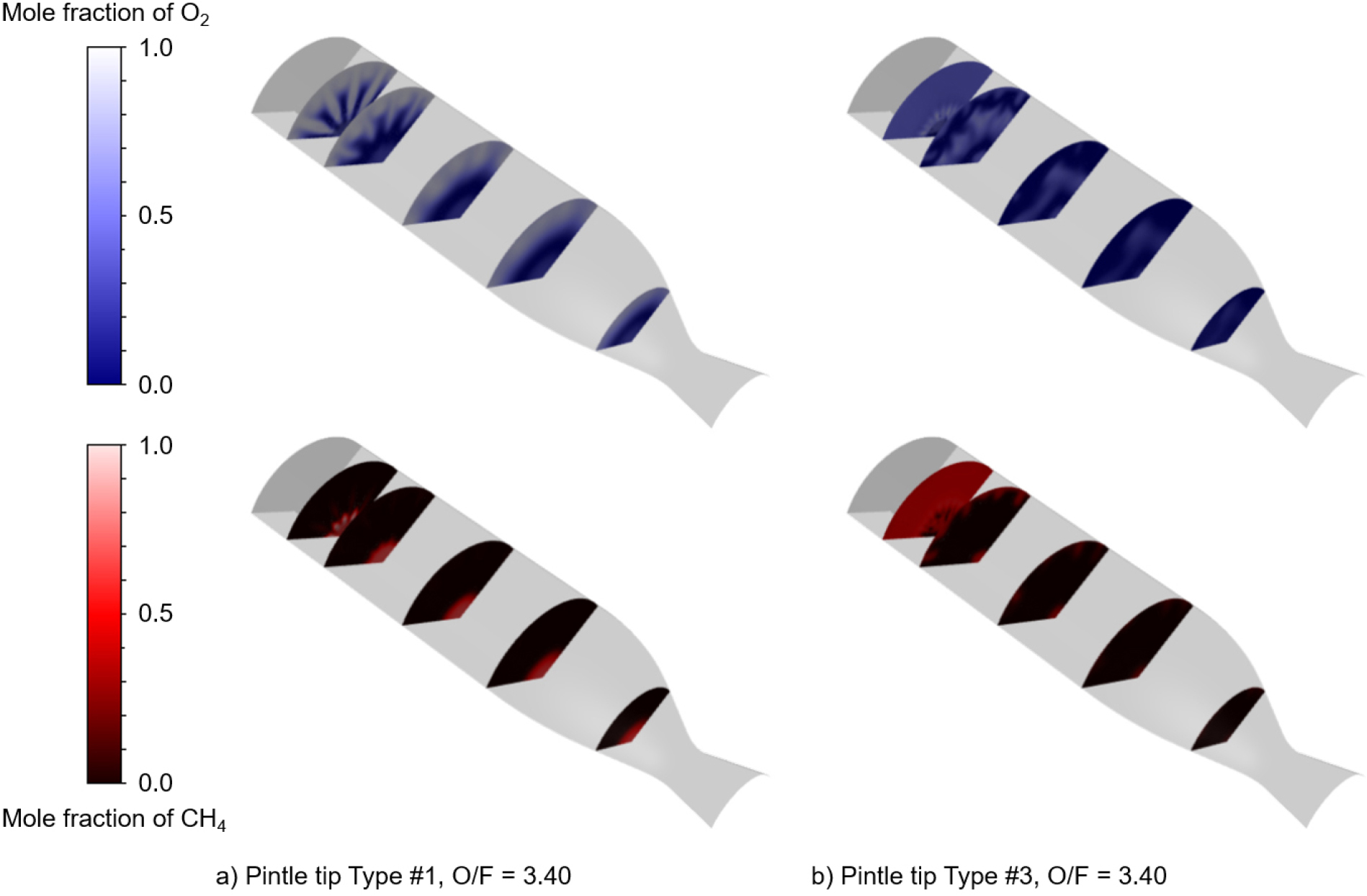
The BF varied depending on the pintle tip type, increasing from 0.174 to 0.347 as the pintle tip type changed from #1 to #3. Correspondingly, c* efficiency also increased. This result can be interpreted from two perspectives. First, it can be attributed to an increase in the interaction area between the oxidizer and fuel due to the increased BF as shown in Fig. 7[25], which subsequently enhanced mixing performance and c* efficiency. Secondly, the increased BF and consequently decreased IMR may have resulted in more efficient liquid radial flow atomization by the axial gaseous flow, thus improving the c* efficiency.
Fig. 7 shows the mole fraction contours of O2 and CH4 for different BFs at a fixed mixture ratio of 3.40. For Type #1, which has a small BF (0.174), the injected O2 impinges on the combustor inner wall, with a significant portion proceeding along the wall towards the nozzle. Simultaneously, CH4 is injected axially and flows along the central axis of the combustor, indicating insufficient mixing between O2 and CH4. On the other hand, for Type #3, which has a relatively larger BF of 0.347, O2 and CH4 are uniformly distributed in the front part of the combustor. Due to their active mixing and reaction, the mole fraction of each significantly decreases towards the rear of the combustor. From these observations, it can be concluded that an increase in BF can enhance propellant mixing performance, thereby improving combustion efficiency. However, it is difficult to distinguish whether the primary cause is the increased interaction area between the oxidizer and fuel, or the momentum ratio reaching an optimal value. Further research is necessary to investigate this by fixing either the momentum ratio of the BF while varying the other.
3.3 Effects of Mixture Ratio
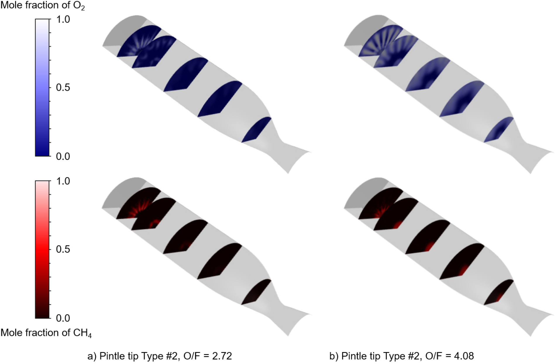
The c* efficiency also varied with the mixture ratio. For all pintle tip types, higher c* efficiency was observed at lower mixture ratios. This indicates that at higher mixture ratios, the interaction between the oxidizer and fuel is insufficient. Conversely, it can be inferred that better interaction occurs at lower mixture ratios, leading to higher c* efficiency.
This can also be observed from the distribution of oxidizer and fuel in the combustor. Fig. 8 shows the mole fraction contours of O2 and CH4 for different mixture ratios when using pintle tip Type #2. When the mixture ratio is 2.72, O2 and CH4 are distributed in the front part of the combustor, and their mole fractions distinctly decrease towards the rear as the chemical reaction occurs. However, at a mixture ratio of 4.08, O2 reaches near the combustor inner wall in the front section and is partially present even close to the nozzle. CH4 also remains distributed along the combustor’s central axis, indicating that the mixing and reaction between O2 and CH4 are limited in this case. Therefore, it can be considered that the combustion efficiency of pintle injectors is influenced not only by the mixture ratio itself but also by the momentum ratio, which varies with the mixture ratio.
4. Conclusion
In this study, the effects of injection conditions on combustion efficiency of a multi-slit type gas-liquid pintle injector were explored. In summary, the following conclusions were derived.
(1) The c* efficiency increased as the momentum ratio decreased. Notably, the highest c* efficiency was not observed at a momentum ratio of 1. This stands in conflict with TRW’s results, implying that the momentum ratio exhibiting maximum combustion efficiency in gas-liquid pintle injectors is not unity. While a wide range of momentum ratios was investigated, the momentum ratio with the highest combustion efficiency could not be identified, thus necessitating further research.
(2) The blockage factor significantly affected the combustion efficiency of the multi-slit type gas-liquid pintle injector. As the blockage factor increased from 0.174 to 0.347, the combustion efficiency also increased. This indicates that the mixing between O2 and CH4 improved due to the increased blockage factor. Furthermore, with a fixed propellant mass flow rate and mixture ratio, an increased blockage factor causes a decrease in the momentum ratio. This reduced momentum ratio may have improved the interaction between the oxidizer and fuel.
(3) The mixture ratio also affected the combustion efficiency of the multi-slit type gas-liquid pintle injector. Regardless of the blockage factor, the combustion efficiency increased as the mixture ratio decreased from 4.08 to 2.72. This suggests that, within the cases explored in this study, the radial flow momentum was excessively high compared to the axial flow momentum. This imbalance prevented sufficient interaction between the oxidizer and fuel at higher mixture ratios, leading to higher combustion efficiency at lower mixture ratios.
The results of this study raise questions about TRW’s design criteria for gas-liquid pintle injectors and highlight the necessity for further research into combustion efficiency under more comprehensive and broader injection conditions, such as momentum ratio, blockage factor, and mixture ratio. In addition, this study was conducted based on RANS simulation; therefore, high-fidelity numerical simulations are necessary for a more accurate prediction of combustion efficiency.
