1. Introduction
2. Requirements for the Propulsion System
2.1 Mission Definition
2.2 Type of thruster
3. Design of the Ion thruster
3.1 Grid
3.2 Plasma Generator
4. Conclusion & Future Work
1. Introduction
The demand for microsatellites has been steadily increasing due to their compact size and ease of development. In particular, multiple microsatellites can be utilized to replace the mission of a single medium- or large-sized satellite, offering advantages such as a relatively short development period and reduced launch costs. These benefits contribute to enhanced scalability and flexibility in mission design.
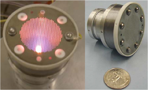
A propulsion system is essential for advanced space missions such as satellite orbital transfer and deep space exploration. Traditionally, satellites have been equipped with cold gas thrusters or chemical propulsion systems; however, electric propulsion systems have recently emerged as a promising alternative due to their high specific impulse. Electric propulsion systems consume less propellant than cold gas thrusters and chemical propulsion systems, enabling missions that require a high delta-v. Furthermore, their low thrust can also provide an advantage in terms of precise control compared to other propulsion systems [1]. Recently, research on the development of low-power electric thrusters has been actively carried out to apply electric propulsion systems to microsatellites. In particular, efforts have been made to miniaturize Hall Effect Thrusters (HETs) and Gridded Ion Thrusters (GITs), which offer high specific impulse as shown in Table 1. For instance, as shown in Fig. 1, Miniature Xenon Ion Thruster (MiXI) is a 3 cm-diameter miniature ion thruster developed by the California Institute of Technology and the Jet Propulsion Laboratory (JPL), designed for various space missions and experimentally validated for its performance. Due to its compact size and low thrust-induced noise, it is expected that the low-power ion thruster would be suitable for controlling microsatellites weighing less than 100 kg [2].
In this study, the mission for a 6U CubeSat was determined and the propulsion system requirements were also derived to enable operation with argon as the propellant and 20 W of RF power, with the objective of achieving a thrust of approximately 0.3 mN and a specific impulse of 1500 s. A comprehensive conceptual design of the RF ion thruster, encompassing the grid system and plasma generation chamber, was carried out in accordance with the given constraints.
Table 1.
2. Requirements for the Propulsion System
2.1 Mission Definition
The use of an electric propulsion system requires sufficient space within the satellite to accommodate batteries and sufficiently large solar panels to generate the required power. The typical configuration of a CubeSat is shown in Fig. 2, and its specifications are presented in Table 2. In this study, a 6U CubeSat was selected, with the assumption that the solar panels could generate a maximum power of 40 W.
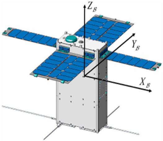
Table 2.
Physical & power constraints of CubeSat [8].
| Size of CubeSat | Mass [kg] | SP power [W] | Battery capacity [W・hr] |
| 1U | 1.3 | 10 | 19.2 |
| 3U | 4 | 26 | 38.5 |
| 6U | 12 | 40 | 77 |
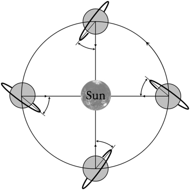
The power required to operate the electric propulsion system is generated from the solar panels. The longer the solar panels face the Sun, the more power they can generate, which enables prolonged thrust production. Thus, a sun-synchronous orbit with a Local Time of the Ascending Node (LTAN) of 6:00 AM, known as a dawn-dusk orbit, was selected as the mission orbit. As illustrated in Fig. 3, this orbit ensures that the satellite’s orbital plane remains perpendicular to the direction of sunlight, allowing for continuous power generation throughout the entire orbit. By setting the mission orbit as a circular orbit at an altitude of 500 km, the corresponding orbital inclination is 97.4°. Furthermore, the primary perturbations considered in low Earth orbit are gravitational forces due to gravitational harmonics and atmospheric drag. In particular, atmospheric drag continuously decreases the altitude of the satellite. To compensate for this, a thruster is necessary to increase the satellite’s orbital velocity, thereby restoring it to the target altitude.
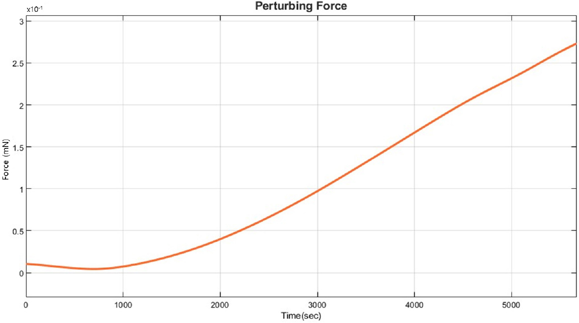
The required thrust was determined by analyzing the external force induced by atmospheric drag using the Spacecraft Dynamics block in Simulink. The external force over one orbital period was computed, and the results are presented in Fig. 4. The analysis shows that as time progresses and altitude decreases, the atmospheric drag increases accordingly. Over one orbital period, the instantaneous external force due to atmospheric drag was computed to range from a minimum of 0.01 mN to a maximum of 0.27 mN.
2.2 Type of thruster
Ion thrusters generate thrust by accelerating plasma formed within a discharge chamber through a grid system subjected to an applied voltage. Ion thrusters can be classified into Direct Current (DC), Radio Frequency (RF), and Microwave types based on their plasma generation method [9]. Among these, the RF method was selected for this study as it has structural advantages and does not require a hollow cathode in the plasma generation process.
Argon was selected as the propellant for this study due to its various advantages, including cost-effectiveness. Like xenon and krypton, which are the most commonly used propellants in electric propulsion systems, argon belongs to Group 18 of the periodic table, making it chemically inert and non-reactive. Additionally, it is non-toxic, ensuring safety during handling and refueling. The atomic mass of argon is 39.938 AMU, whereas that of xenon is 131.293 AMU, meaning argon has a significantly lower mass. Consequently, when the same voltage is applied to the ion thruster grid, argon achieves a higher exhaust velocity compared to xenon. Furthermore, argon is significantly more cost-effective than xenon [10], providing a major economic advantage amid the growing development and deployment of CubeSats and microsatellites. Here, the requirements for the propulsion system, based on the above considerations, are summarized in Table 3.
3. Design of the Ion thruster
3.1 Grid
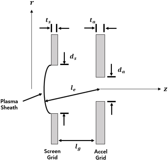
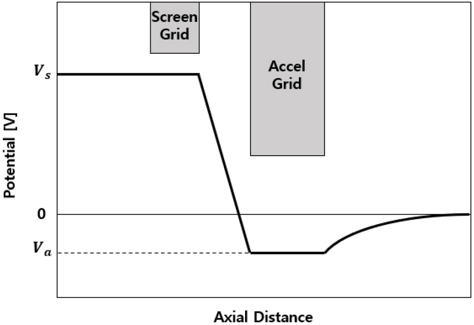
The number of grids in an ion thruster can be designed as either two or three, depending on the intended application. In this study, a two-grid system was selected due to its structural and circuital simplicity and Fig. 5 illustrates the structure of a two-grid system. The screen grid confines electrons within the discharge chamber and aligns ions with the apertures of the accelerator grid. The accelerator grid, which is maintained at a lower voltage than the screen grid, serves to accelerate the ions. Fig. 6 presents a typical axial potential distribution of an ion thruster. To achieve the desired thruster performance, the potential applied to each grid must be appropriately determined.
The beam voltage refers to the potential difference between the screen grid and the beam potential generated within the thruster. This voltage determines the acceleration of the ions, directly influencing the thruster performance based on the principle of energy conservation, the beam voltage can be expressed as Eq. (1). The actual specific impulse must consider the thrust correction factor (𝛾) and the mass utilization efficiency (), leading to the formulation expressed in Eq. (2). Here, it is assumed that only singly charged ions are produced during the plasma generation process. Furthermore, assuming a beam divergence angle of 15°, the thrust correction factor is set as 0.97 and the mass utilization efficiency is assumed to be 0.3 based on an RF ion thruster of similar size [11]. Taking these factors into consideration, the required beam voltage to achieve the target specific impulse of 1500 s is determined to be 534 V.
The ion beam is neutralized downstream of the accelerator grid by a neutralizer, ensuring charge balance. However, due to the significantly higher mobility of electrons compared to ions, they may flow back into the discharge chamber, a phenomenon known as electron backstreaming. This effect can lead to unnecessary power loss and potential thermal damage to the thruster. To minimize this issue, the accelerator grid must be maintained at a sufficiently negative voltage to limit the backstreaming electron current to less than 1% of the ion beam current. The ratio between the total voltage applied across the grids and the beam voltage can be expressed as Eq. (3) where the ratio is typically set within the range of 0.8 to 0.9 [12]. A value of 0.8 was set for the grid design, resulting in a total grid voltage () of 667 V and an accelerator grid voltage () of -133 V. Considering additional operational margins, the final selected grid voltages were screen grid voltage () of 550 V, accelerator grid voltage of -150 V, total grid voltage of 700 V. These values ensure stable thruster operation while preventing electron backstreaming and potential thruster damage.
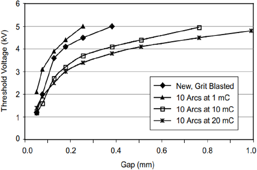
A significant voltage difference across the narrow gap between screen grid and accelerator grid can lead to arc discharge. To prevent this, the materials used for the grids must satisfy the condition given in Eq. (4). Typically, for stable thruster operation, the electric field strength is set to be less than half of the breakdown field strength . Molybdenum, which has a low sputtering rate, was selected as the grid material. The breakdown field strength of molybdenum as a function of the grid gap () can be determined from Fig. 7. Considering the previously calculated total voltage of 700 V and the manufacturability of the grids, a grid gap of 0.5 mm was selected, resulting in an electric field strength of = 1400 V/mm.
Using the typical grid geometry parameter ratios, the screen grid hole diameter (), screen grid thickness (), accelerator grid hole diameter (), and accelerator grid thickness () were determined [12]. The final grid dimensions are summarized in Table 4.
Table 4.
Typical geometry parameter ratio & Grid geometry.
| Typical geometry parameter ratio [12] | Grid geometry | |||
| Parameter | Value | Parameter | Value | |
| 1.0 | 0.5 mm | |||
| 0.5 | 1.0 mm | |||
| 0.6 | 0.6 mm | |||
| 0.2 | 0.2 mm | |||
| 0.4 | 0.4 mm | |||
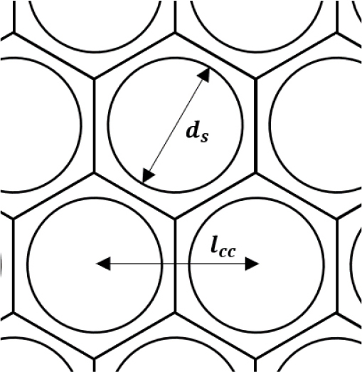
The maximum thrust density that an ion thruster can generate is expressed by Eq. (5). The transparency () represents the ratio of the current passing through the screen grid apertures to the total current flowing through the screen grid in the discharge chamber. As shown in Fig. 8, if a hexagonal unit cell is assigned to each aperture, the transparency can be expressed by Eq. (6). Typically, the transparency is set to = 0.67 [12]. Here, represents the center-to-center distance between apertures, which is determined to be 1.16 mm.
The maximum current density () in an ion thruster is governed by Child-Langmuir’s law, which is expressed in Eq. (7). This equation represents the maximum ion current density that can be transmitted between two electrodes, considering space-charge-limited flow. The sheath thickness between the two electrodes can be determined using Eq. (8) and the parameters listed in Table 6. By applying these relationships, the sheath thickness () was calculated to be 0.86 mm. Substituting the total grid voltage of 700 V and the mass of an argon atom (6.63 × 10⁻²⁶ kg), into Eq. (7), the maximum current density () was determined to be 0.216 .
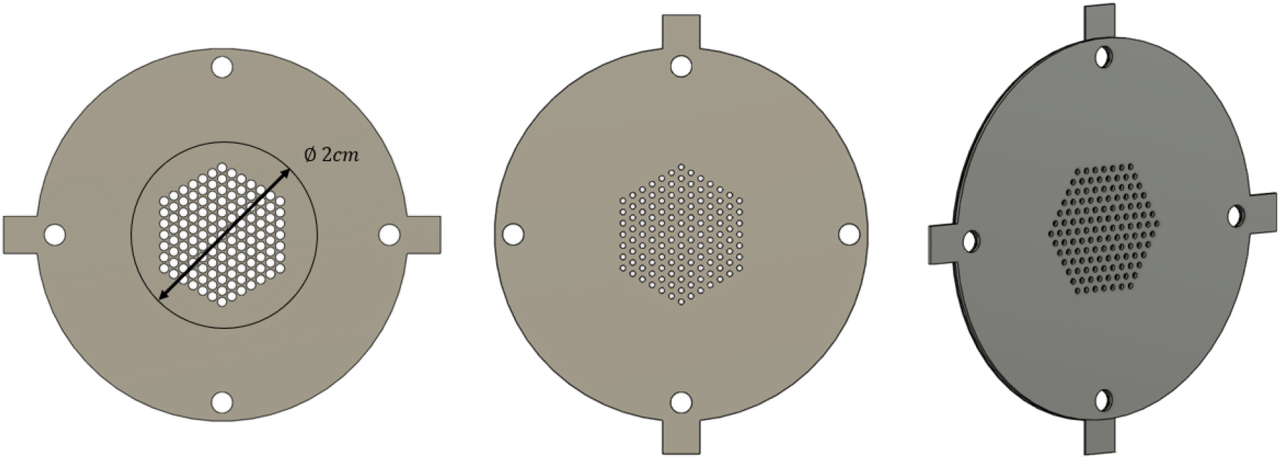
Using the maximum thrust density derived from Eq. (5), the required number of grid apertures necessary to achieve the target thrust of 0.3 mN was calculated. To meet the required thrust, a total of 120 grid apertures were determined to be necessary. However, considering layout constraints and additional operational margins, the final grid configuration was optimized. The finalized grid geometry and performance parameters are summarized in Table 5. Additionally, Fig. 9 illustrates the designed grid structure.
Table 5.
Grid geometry & Performance of the designed thruster.
| Parameter | Value |
| Grid diameter () | 20 mm |
| The number of apertures | 127 |
| Maximum thrust () | 0.32 mN |
| Maximum beam current () | 7.77 mA |
3.2 Plasma Generator
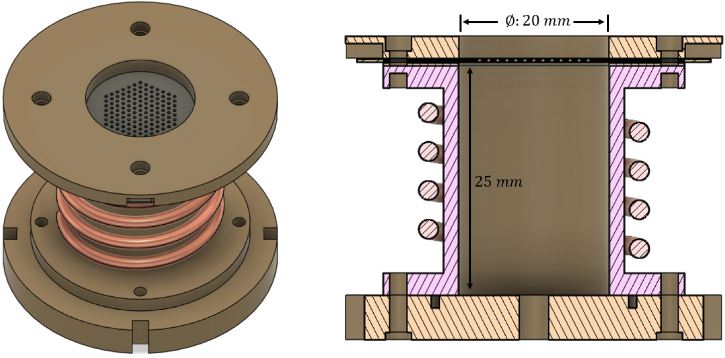
Among the available discharge chamber designs, the cylindrical type was selected due to its ease of manufacturing and stable plasma generation within the chamber. Fig. 10 illustrates the cross-sectional structure of the cylindrical RF ion thruster. A ceramic material with excellent insulating properties and high thermal resistance, specifically Al2O3, was selected for the discharge chamber. The chamber diameter was set to 2 cm, matching the diameter of the previously designed grid system.
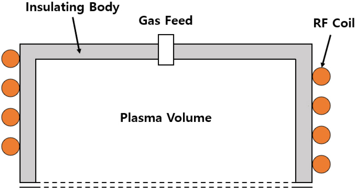
The plasma generation principle using RF (Radio Frequency) can be explained through Maxwell’s equations. Eq. (9) represents one of Maxwell’s equations, describing the rotationally induced electric field generated as the magnetic field varies over time, which governs the fundamental plasma generation process in RF ion thrusters. When RF power is applied to the coil surrounding the discharge chamber, an axial induced magnetic field () is generated inside the chamber. This time-varying magnetic field, in turn, induces an azimuthal electric field (), which accelerates the free electrons within the discharge chamber. As these accelerated electrons gain energy, they collide with neutral atoms, leading to ionization and plasma generation. This mechanism enables the efficient generation of plasma within the chamber, ensuring a stable ion source for the thruster.
During the plasma generation process, collisions between neutral molecules and electrons within the discharge chamber are essential for ionization. The probability of an electron making a collision (P) is given by Eq. (10), which characterizes the likelihood of electron-neutral collisions. From the equation, the minimum required pressure within the discharge chamber can be determined using Eq. (11). This calculation ensures that the neutral gas density is sufficient to maintain a stable plasma discharge, enabling efficient ionization for thruster operation. The derived pressure requirement provides a critical design constraint for the propellant feed system, ensuring optimal plasma generation conditions within the RF discharge chamber.
The minimum pressure required for RF plasma discharge is generally known to be , and it is assumed that the probability of collisions between electrons and neutral atoms is approximately 10%. For the selected propellant, argon, with an atomic radius of 0.88 Å, the minimum discharge chamber length was calculated to be 1.35 cm based on a neutral gas temperature of 298 K. Considering additional design margins, the initial internal length of the discharge chamber was set to 2.5 cm. As long as the minimum pressure condition is satisfied within the discharge chamber, plasma generation can occur even with a small number of free electrons present.
To sustain plasma discharge, a sufficient supply of neutral gas must be fed into the discharge chamber. The required neutral gas flow rate for plasma discharge can be estimated using Eq. (12), (13), (14), (15) as described in [13]. The flow rate of neutral gas that is not ionized and escapes the discharge chamber () is the gas injected into the discharge chamber () minus the gas particles that form the beam current (), defined by Eq. (12). (Here, represents the velocity of neutral gas particles, calculated using the Maxwell-Boltzmann thermal velocity distribution. At 298 K, the velocity for argon gas is 397 m/s. denotes the grid area and represents the grid transparency. The clausing factor () was assumed to be 0.5 [13].) Eq. (13) represents the mass utilization efficiency defined as the ratio of the injected neutral gas that is ionized and exits as beam current. Eq. (14) describes the neutral gas density within the discharge chamber (), considering both the incoming neutral gas and the ions that are ionized and expelled through the grids. To generate a thrust of 0.3 mN while maintaining an internal chamber pressure of 10-3 Torr and a mass utilization efficiency of 0.3, the required neutral gas flow is approximately 0.35 sccm. The corresponding conditions are summarized in Table 6.
Table 6.
Values required to generate 0.3 mN while maintaining an internal pressure of 10-3 Torr.
| Parameter | Value |
| Discharge chamber pressure () | 10-3 Torr |
| Neutral gas density () | 3.36 × 10¹⁹ m-3 |
| Beam current () | 7.35 mA |
| Mass utilization efficiency () | 0.29 |
| Flow rate () | 0.35 sccm |
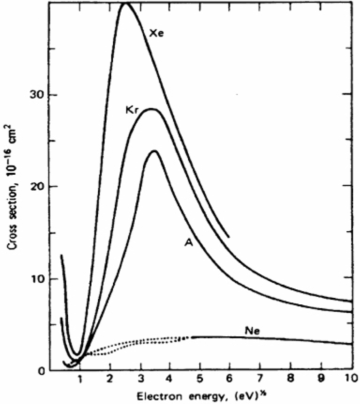
The strength of the induced magnetic field (B) generated by RF discharge is closely related to the radial velocity of ions. As the magnetic field strength increases, the ion current directed toward the chamber walls decreases, thereby reducing discharge losses and improving the overall efficiency of the thruster. The radial velocity of ions can be expressed using Eq. (16)[13]. The electron temperature () and electron density () herein were assumed to be 4 eV and 2 × 10¹⁸ [-3], respectively, based on reference data from RF ion thrusters operating under similar pressure conditions as the designed ion thruster [14]. The electron-neutral collision frequency () can be estimated using Eq. (17), which incorporates the mean thermal velocity (), neutral gas density (), and the average collision cross-section () [15]. The neutral gas density was taken as 3.36 × 10¹⁹ [-3], based on previous calculations, while the average collision cross-section was determined to be 0.8 × 10⁻²⁰ [2], as referenced in Fig. 11[15]. The electron-ion collision frequency () and the Coulomb logarithm (lnΛ) can be expressed using Eq. (18) and (19), respectively [16]. Here, represents the discharge chamber radius, which is set to 1 cm [13].
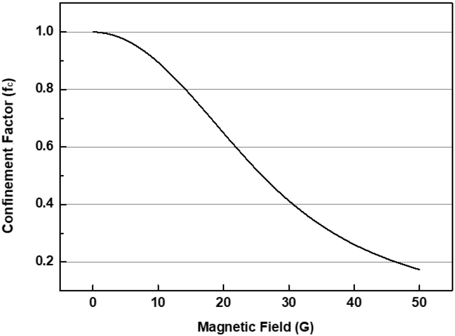
Eq. (20) represents the ratio of the radial ion velocity () to the Bohm velocity (), indicating the extent to which the magnetic field confinements ion motion. As shown in Fig. 12, an increase in magnetic field strength leads to a reduction in ion velocity, thereby decreasing the ion current lost to the chamber walls. In this study, the confinement factor () was set to be less than 0.5, leading to a target magnetic field strength of 26 G. In addition, Eq. (21) describes the magnetic field strength (B) generated inside the discharge chamber, which is determined by the number of coil turns and the current applied. The coil was designed with 4 turns, and a current of 13 A was required to generate a 26 G magnetic field. Considering the allowable current capacity and the discharge chamber length, AWG 10 copper wire was selected for the coil.
When high-frequency power is applied to the coil, the skin effect occurs, causing current to concentrate on the conductor’s surface. This phenomenon arises because the impedance increases at the conductor’s core while decreasing at the surface, thereby restricting power delivery to the inner regions of the conductor. Eq. (22) represents the skin depth (𝛿) caused by the skin effect, indicating how deeply the RF power can penetrate and it is observed that this is influenced by the frequency of RF coil. In the design of RF ion thrusters, the skin depth is typically set to be 1/2 to 2/3 of the discharge chamber radius [17]. In general, RF ion thrusters are commonly known to operate in the frequency range of 0.5-5 MHz [18]. In this study, the frequency was determined based on the method described below. The plasma conductivity (𝜎) in low-density plasma with a low ionization rate can be expressed using Eq. (23)[15]. Using the previously derived values, the plasma conductivity was calculated to be approximately 15,700 S/m which is on the same order of magnitude as values reported in the literature [19]. At a coil frequency of 0.4-0.6 MHz, the resulting skin depth was 5.2-6.3 mm. This value satisfies the range of 5.0-6.7 mm, which corresponds to 1/2 to 2/3 of the discharge chamber radius.
4. Conclusion & Future Work
In this study, a conceptual design of an RF ion thruster for microsatellites was conducted. The aerodynamic drag acting on a 6U CubeSat in a dawn-dusk orbit at an altitude of 500 km was analyzed, with values ranging from 0.01 to 0.27 mN per orbital period. To compensate for this drag, an RF ion thruster was designed with a target specification of a thrust of 0.3 mN and a specific impulse of 1500 s, and RF power of 20 W using argon propellant. The final thruster configuration and its specifications are presented in Fig. 13 and Tables 7, 8. The designed thruster is planned to be validated through fabrication and experimental testing.