

1. Introduction
2. DCR Combustor Model
2.1 Operating Conditions and Configurations of DCR
2.2 Numerical Modeling of DCR
3. Flame Structures and Combustion Performance in DCR
3.1 Combustion Modes and Flame Structures
3.2 Dependency of Combustion Performance on Divergence Angle
3.3 Effect of the Constant-Area Combustor Length
4. Conclusion
1. Introduction
The successful test flight of the X-51A began a new era of powered hypersonic flight for practical applications. The X-51A’s dual-mode ramjet (DMR) engine with liquid fuel distinguishes it from a previous scramjet vehicle. The DMR engine starts in a thermally choked ramjet mode at supersonic launching speed and then accelerates to a hypersonic cruising condition operating in scramjet mode. The DMR can achieve a practical flight time and range by using liquid fuel. The liquid fuel flows through a regenerative cooling passage, and superheated fuel is injected into the combustor in a gaseous phase [1,2].
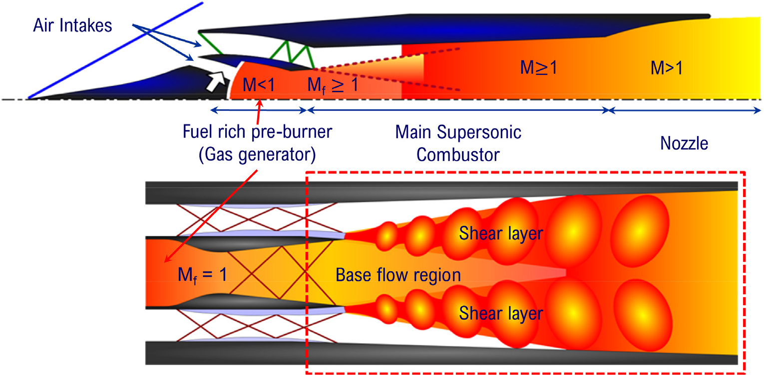
While the DMR is attractive for reusable systems, the dual combustion ramjet (DCR) by Billig et al. [3] would be more affordable for expendable systems. Fig. 1 shows the schematics of DCR operation. A part of the incoming air is compressed to a subsonic condition for fuel-rich combustion in the gas generator. The pre-burned fuel is injected into the supersonic combustor at high speed. The high-temperature gas-phase fuel mixes with the supersonic air and burns easily. The fuel-air mixing on the supersonic turbulent shear layer is the major mechanism of combustion in the DCR engine, which is conceptually very similar to a rocket-based combined cycle (RBCC) engine.
Previous research work [4] suggested performance estimation of the combined-cycle engine applying two-step combustion and realized the need of computational simulation in detail. Some supersonic combustion studies employing the co-flow of fuel and air can be related to the combustion in DCR [5,6,7,8]. However, the focus has mostly been on understanding the fundamental characteristics of supersonic combustion. Research on the turbulence characteristics of supersonic combustion is still at an early stage due to the limitations in visualization, measurement, and computing capabilities. In terms of numerical investigation of mixing and combustion, there are a few numerical results only of hydrogen/air reaction [9,10]. The present study investigates the characteristics of the supersonic turbulent combustion in DCR, using hydrocarbon fuel, to understand the combustion dynamics and stability by means of a high-resolution numerical analysis.
2. DCR Combustor Model
2.1 Operating Conditions and Configurations of DCR
One approach to burning heavy liquid hydrocarbon fuel easily in supersonic flow is to pre-burn the fuel with a small amount of air. It is known that the optimum air ratio for the pre-burner and the main combustor is approximately 1:3. Thus, the equivalence ratio in the pre-burner is more than 3.0 to maintain an equivalence ratio less than 1.0 in the main combustor. Under these conditions, the pre-burned gas is mainly composed of carbon monoxide and hydrogen with nearly the same volumetric ratio and an exit temperature of around 1,000 K [3]. The cracked fuel at this high temperature improves the combustion drastically in the harsh combustion conditions in supersonic flows.
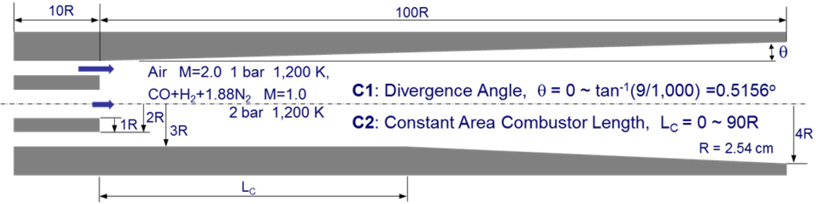
This study considers a fuel-rich pre-burning of heavy hydrocarbon fuel, CnH2n. Assuming an equivalence ratio of 3.0, the composition at the pre-burner exit is assumed to be CO+H2+1.88N2. For simplicity, the pre-burned fuel is also assumed to be injected through a sonic nozzle at static temperature and pressure of 1,200 K and 0.2 MPa, respectively. The air (O2+3.76N2) is flowing through the intake diffuser at Mach 2.0, static temperature of 1,200 K, and pressure of 0.1 MPa. This condition roughly corresponds to a flight Mach number of 6 at an altitude of 20-30 km, depending on the intake design.
Considering the realistic size of the engine, the combustor is assumed to have a fuel port radius R of 2.54 cm with a lip thickness of R as well, which separates the fuel and air stream. The Reynolds number for the injector diameter is 2.05 × 10⁵. The radius of the main combustor is assumed to be 3R, the length of the main combustor is 100R. Two different configurations are considered for parametric studies of flame stabilization. One configuration is a divergent combustor with various values of the divergent angle 𝜃 ranging from 0 to tan-1 (9/1,000). The other configuration is a combustor with a constant area combustor section of length LC, which ranges from 0 to 90R. An exit radius of 4R is assumed for the combustor, which corresponds to a divergence angle of tan-1 (10/1,000) for the case of LC = 0. The flow conditions and configurations are summarized in Fig. 2.
2.2 Numerical Modeling of DCR
The turbulent combustion was analyzed by solving the fully coupled governing equations of species, momentum, and energy conservation. Turbulence was modeled by Menter’s SST-based hybrid RANS/LES model, which captures the boundary layer in RANS mode but returns to LES mode at the shear layer and separated flow region. A second order time accurate and fifth-order accurate optimized multi-dimensional limiting process (oMLP) scheme [11,12] is used to capture the turbulence eddy dynamics. Further details about the physical models and solution procedures are discussed in a previous paper along with a validation study for supersonic combustion [13].
The high-temperature CO/H2 oxidation mechanism is from Singh and Jachimowski [14] and includes eight reacting species (CO, CO2, O, O2, H, H2, OH, H2O) and inert nitrogen (N2). HO2 and H2O2 are neglected since the incoming temperature is sufficiently high for auto-ignition. The computational domain is shown in Fig. 2. The computational grid has 2,401 × 221 elements for the main combustor, 97 × 81 elements for the air inlet, and 97 × 61 elements for the fuel inlet. The computational grid is clustered at the wall surface while maintaining uniform grid spacing around the first half of the combustor using 3/4 the number of grids, but the grid is longitudinally extended grid in the divergent section using one-fourth of the grids. Time integration is carried out for 300,000 time-steps by using a CFL number of 2.0. Maximum 4 sub-iterations are allowed at each time-step to ensure second order time accuracy. Those correspond to a physical time step of 67.0 ns and operation time of 20.1 ms after the injection. Time averaging is carried out for the latter half of 150,000 time-steps.
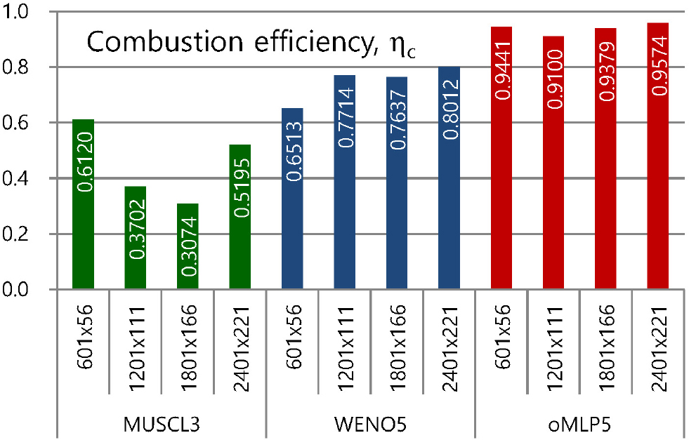
As a preliminary step of the grid independence study for further studies, the combustion efficiency of the time-averaged results was examined at the combustor exit for the case of LC = 50R. Fig. 3 shows the combustion efficiency results obtained using four levels of different grids with three different numerical schemes. In the case of the third-order accurate monotonic upwind scheme for conservation laws (MUSCL3), the combustion efficiency remained low for all grid systems. Interestingly, the coarse grid (level 1) shows the best value. The combustion efficiency decreases with finer grids but recovers when using the finest grid (level 4). It is understood that larger numerical diffusion facilitates the mixing and combustion in the coarse grid with better combustion performance. The combustion efficiency of the fifth-order accurate weighted essentially non-oscillatory (WENO5) scheme shows more monotonic variation since the combustion efficiency increases as the grid resolution becomes finer. However, the improvement in combustion efficiency is slowing down and is limited to 0.8, even with the finest grid.
The results clearly demonstrate the capability of the multi-dimensional higher order oMLP scheme. Regardless of the grid resolution, the combustion efficiency is maintained well over 0.9, which is much higher than the other schemes on average. The oMLP scheme [11,12] employs the multi-dimensional limiting function that effectively controls the oscillations near shocks and contact discontinuities. Unlike the conventional one-dimensional-based methods such as TVD, ENO, and WENO, which fail to fully account for multi-dimensional flow characteristics and often lead to excessive numerical diffusion or spurious oscillations near shock wave as the dimensionality increases, oMLP provides improved accuracy and stability. The authors [11,12] mentioned that while the MLP interpolation step is about 2.47 to 2.96 times more expensive than the van Leer limiter, the overall elapsed computation time is only 1.15 times longer due to better convergence properties. Additionally, MLP achieves the same level of accuracy with 3 to 4 times fewer grid points, significantly improving resolution while maintaining computational efficiency. As a result, the oMLP scheme demonstrates significantly higher combustion efficiency compared to other numerical schemes, achieving nearly complete combustion with a combustion efficiency of 0.95 at the finest grid level. Therefore, the level 4 resolution with the oMLP scheme is used throughout the following studies.
3. Flame Structures and Combustion Performance in DCR
3.1 Combustion Modes and Flame Structures
DCR combustors with divergence angles of 𝜃 = tan-1 (9/1,000) and 𝜃 = 0 were examined. Fig. 4 and 5 show the results of two extreme cases in the form of instantaneous and time-averaged plots for temperature, density gradient, mixture fraction, scalar dissipation rate (SDR, 𝜒) and flame index (FI) [15,16]. The sonic lines are overlaid with the temperature distribution as a black solid line.
Fig. 4 shows the resulting plots for the divergent combustor. The shear layer development is similar to that of an ordinary jet flame, but the high Reynolds number results in irregular Kelvin-Helmholtz instabilities that further develop into turbulent eddy motions. The difference in Mach number between the air and fuel flow makes a distinct shock train pattern with Mach disks. At the beginning of the shock train, the strong shock wave interacts with the turbulent shear layer while distorting the distribution of the SDR and other variables. However, the strength of the shock wave becomes weaker further downstream, and the interaction with the shear layer becomes unnoticeable.
The SDR is high at the beginning but becomes lower and wider with better combustion. However, a very long flame is developed according to the temperature distribution. Thus, some amount of fuel is flowing out of the combustor in an unburned state. Interestingly, FI is always negative along the shear layer, meaning the combustion mostly remains in diffusive mode, in contrast to ordinary non-premixed turbulent combustion and the validation case from a previous study [13]. It is reasoned that the fuel and air promptly react as they mix since the temperature is sufficiently high for both sides, while the fuel is cold in the validation case.
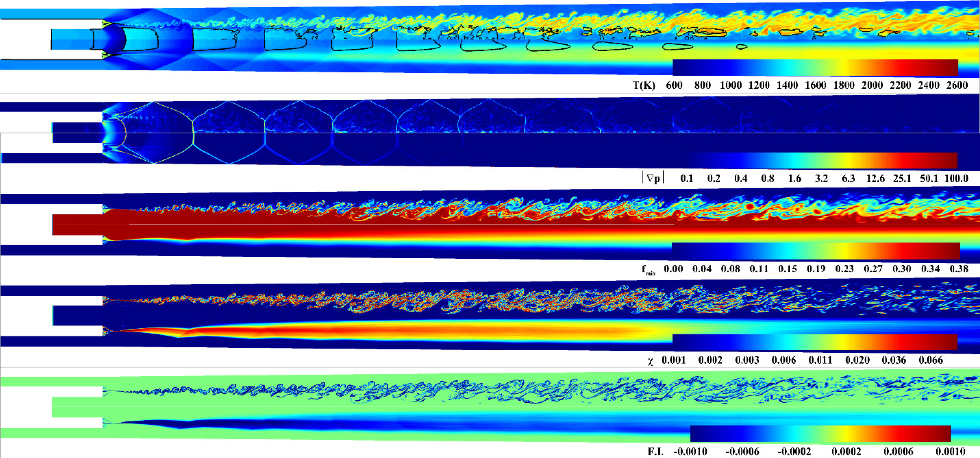
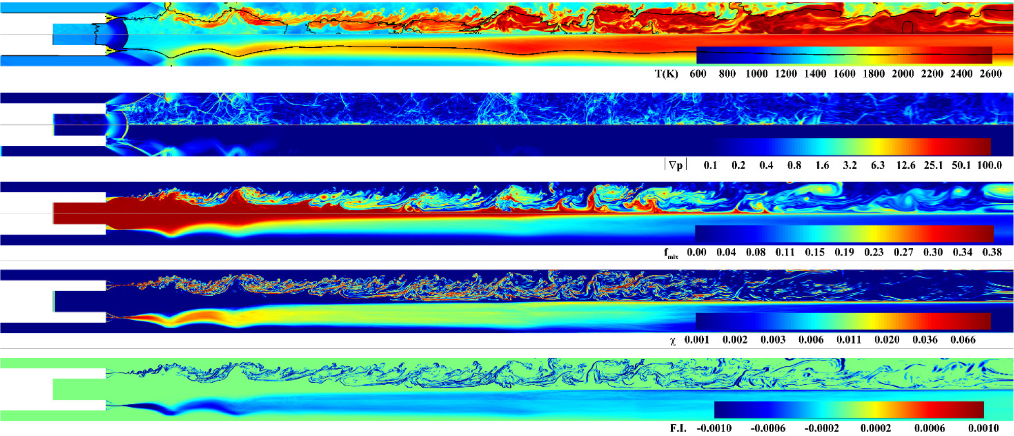
Fig. 5 shows the stabilized results for a constant-area combustor. The combustion is much stronger, and almost all the fuel is consumed before exiting the computational domain. The compression effect by the reduced divergence angle results in high temperature and pressure for better combustion. However, this is not sufficient to account for such drastic changes, since the maximum area ratio for both cases is 1.69 at the combustor exit, and the changes in the thermodynamics properties from the area change are small.
Close examination of the flame development process from the injection indicates that pressure wave interactions are formed by turbulent motions with heat addition in the middle of the combustor. The pressure wave interactions finally couple to the Mach reflection at the combustor wall, which locally results in thermal choking. The Mach reflection reduces the flow speed and SDR, thus greatly enhancing the combustion and heat addition. The heat addition behind the Mach reflection results in the normal shock wave moving forward, near the injector lip. Finally, the flow is stabilized after some transient period, as shown in Fig. 5. Therefore, the coupled effects of compressibility and turbulent flame structures change the mode of combustion to thermal choking. This unsteady process can be observed in the supplemental animation.
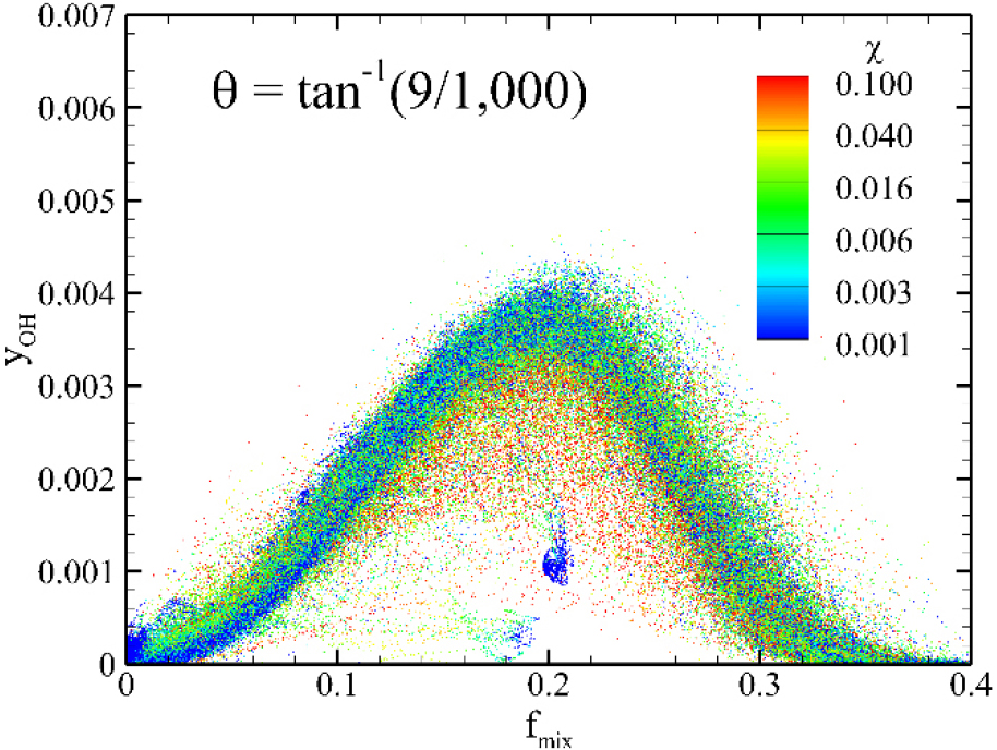
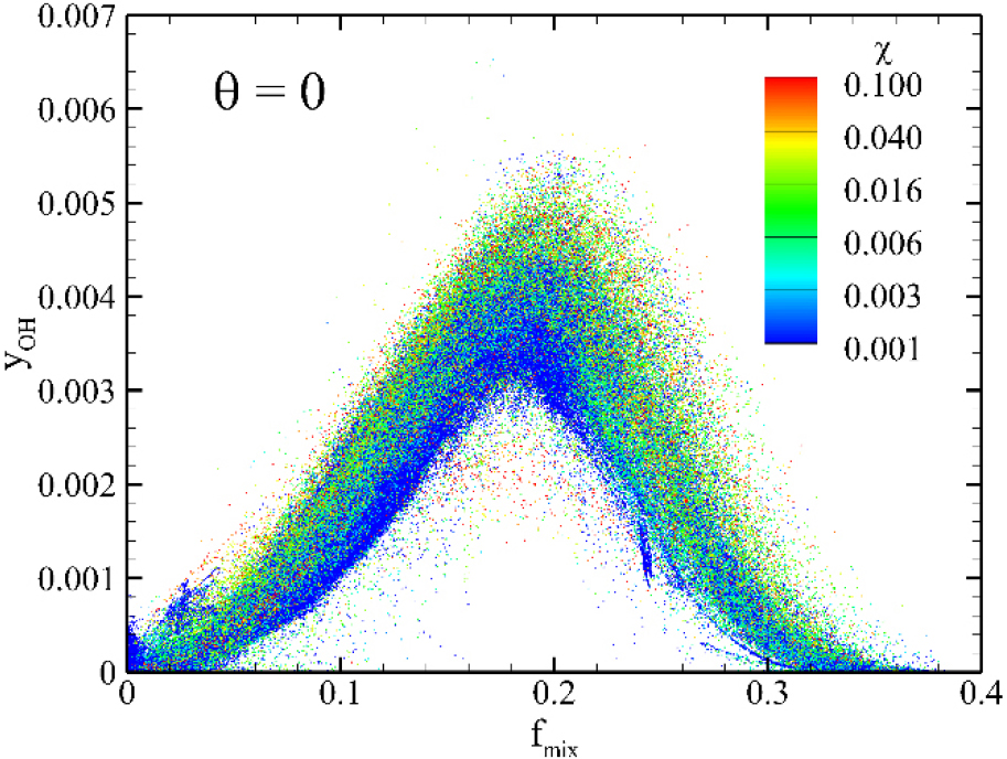
The difference between the two cases is also illustrated in the scatter plots of OH mass fraction in Fig. 6 and 7, with colors representing the SDR. The scatter points in Fig. 6 and 7 include all data points from the level 4 grid across the entire combustor domain. The divergent combustor has a lower peak value, but the flame is still present at high SDR in the upstream region and produces a small amount of OH at the intermediate range of mixture fraction. The blue dotted region in the middle of the plot corresponds to the recirculation region at the injector lip where intermediate products are trapped. The constant-area combustor has a higher OH peak value and a much lower SDR level than the divergent combustor. Due to the Mach reflection, the upstream region has a lower SDR in the blue region with a strong contribution to OH production.
3.2 Dependency of Combustion Performance on Divergence Angle
Fig. 8 shows the temperature contours from the parametric study on the divergence angle. The dependency on the divergence angle is clear in the temperature level. The flame has characteristics of a turbulent lifted flame, and the lifting distance increases with the divergence angle. Nevertheless, it is hard to define the lifting distance because small amounts of fuel and air burn quickly as they mix due to the high temperature of both sides. The phenomenon by this extreme condition would be a different point from a subsonic turbulent lifted flame.
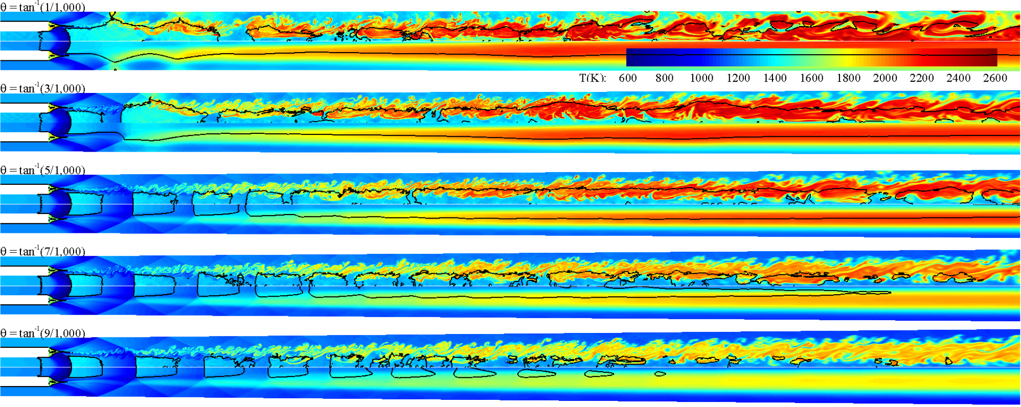
Fig. 9 shows plots of the time-averaged wall pressure. The results for a large divergence angle combustor show a regular saw-tooth pattern that is lower than the incoming pressure and decays gradually. A critical condition is observed at a divergence angle of 𝜃 = tan-1 (4/1,000) for the change of combustion modes to local thermal choking. For the case of 𝜃 = tan-1 (4/1,000), a small peak is observed in the middle of the combustor resulting from the enhanced combustion by the pressure wave interactions from the turbulent combustion. For 𝜃 greater than a value of the critical condition, the peak decays out. However, the peak develops into a strong primary pressure peak for 𝜃 smaller than the critical value while the pressure in the middle of the combustor gradually increases.
The primary pressure peak is sustained by the Mach reflection at the combustor wall. Its location is almost fixed for different divergence angles, but it becomes stronger as 𝜃 becomes smaller. The strength and location of the primary peak are about the same at 𝜃 = 0 and 𝜃 = tan-1 (1/1,000), but the secondary peak is much weaker at 𝜃 = tan-1 (1/1,000). At 𝜃 = tan-1 (2/1,000) and 𝜃 = tan-1 (3/1,000), the strengths of the primary and secondary peaks are much weaker than before. Also, the location of the primary peak occurs further downstream as 𝜃 increases.
The formation of the Mach reflection results in strong pressure fluctuation and combustion enhancement. Fig. 10 shows the results of a Fast Fourier Transform (FFT) analysis of the time-varying pressure at two locations, x = 20R and x = 50R, for the extreme cases of 𝜃 = 0 and 𝜃 = tan-1 (9/1,000). The strength of the pressure wave is a higher order of magnitude for 𝜃 = 0 with several times lower frequency. The pressure wave generated by the turbulent eddy motion becomes stronger due to the enhanced combustion and occasionally forms a shock wave. The strong pressure wave has wider spatial variation and results in low frequency.
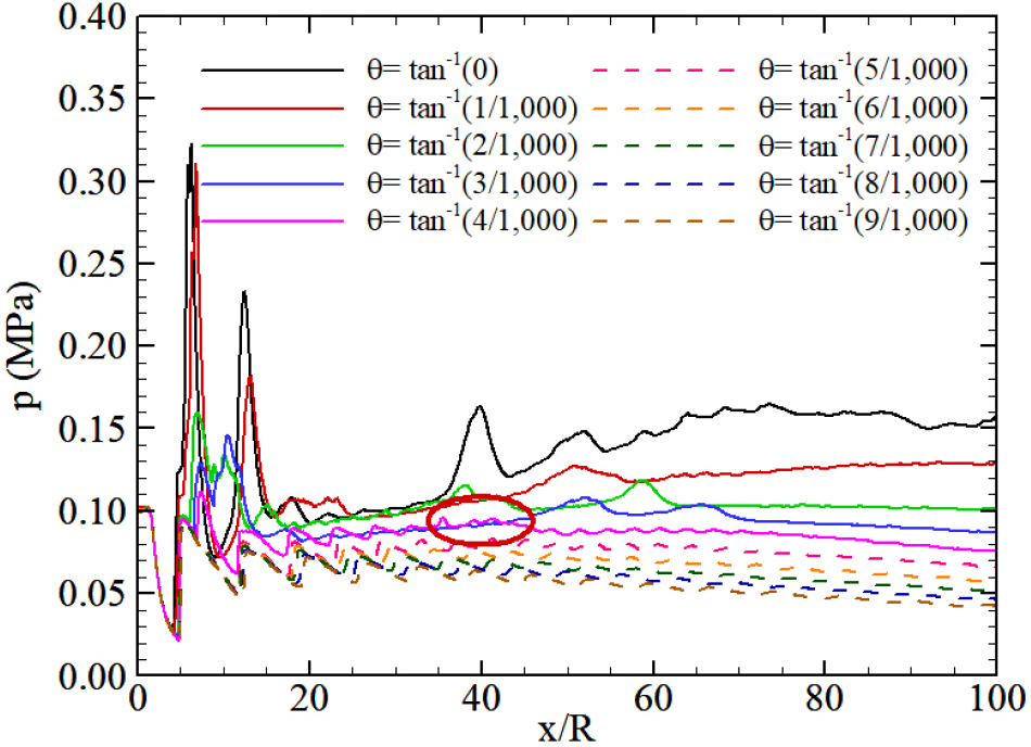
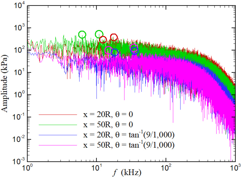
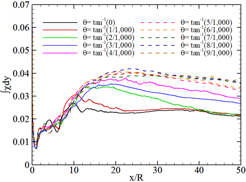
Fig. 11 shows a plot of the SDR for these cases. The SDR is integrated across the cross section of the combustor to account for the longitudinal variation. For the cases of larger 𝜃, the SDR increases gradually until the maximum value is reached around 25R, and then it decreases slowly. Since the SDR is decreasing downstream, the combustion becomes more active. In the case of the Mach reflection formation, the SDR stops increasing behind the pressure peaks, decreases more rapidly, and remains low. This explains the combustion enhancement by the formation of Mach reflection, and the combustion intensity would be uniform over all combustor lengths.
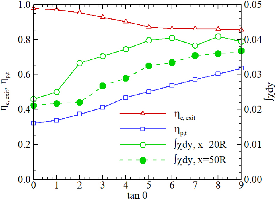
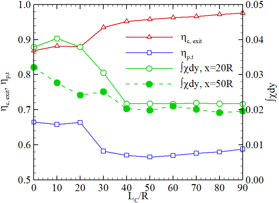
The combustion efficiencies, SDRs at x = 20R and x = 50R, and total pressure recovery () are summarized in Fig. 12. Almost complete combustion (98%) is observed for 𝜃 = 0, but the efficiency decreases to 86% for 𝜃 = tan-1 (9/1,000). Combustion efficiency is inversely proportional to the SDR, while increases inversely with combustion efficiency.
3.3 Effect of the Constant-Area Combustor Length
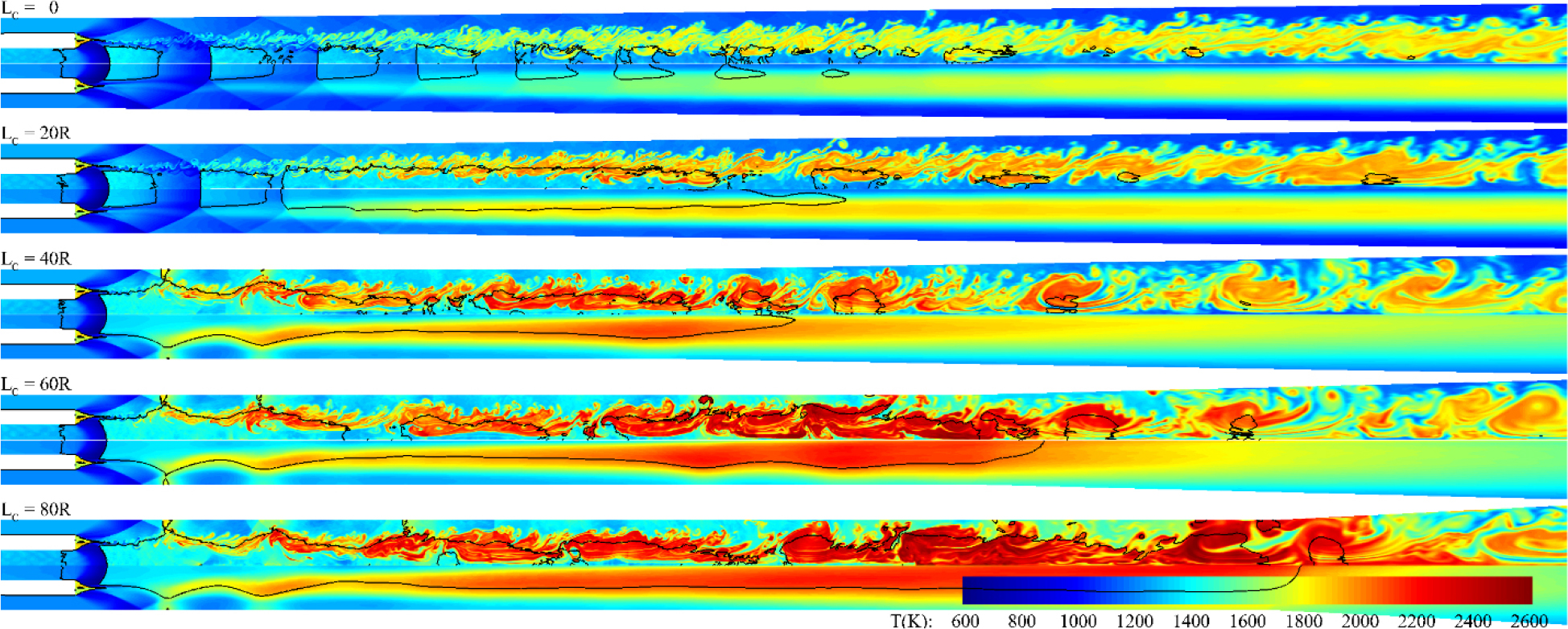
Since the constant-area combustor is quite effective for the enhancement of combustion, another parametric study was carried out by changing the length of the constant-area combustor section LC from 0 to 90R while maintaining the same inlet/exit ratio. The instantaneous and time-averaged temperature distributions are plotted in Fig. 13. The enhancement of combustion with the increase of LC seems to occur as the divergence angle decreases. However, local thermal choking is observed for all cases where LC is greater than 40R. For a quantitative comparison, the combustion efficiency is plotted in Fig. 14. In contrast to the dependency on the divergence angle, a distinct jump occurs around LC = 30R, although there is a gradual increase above this condition.
The SDR decreases quite linearly before the critical condition but is maintained at nearly a constant level after the critical condition. The result implies that there is a critical length of LC where the Mach reflection forms, and the combustion is enhanced. The coupling of pressure waves from the combustion-generated turbulence occurs around this location. Therefore, the Mach reflection can only be formed if LC is long enough. The overall performance does not differ much if LC is sufficiently large. Thus, the compressible effects are fully coupled with the turbulent structures of reacting flows, which form a strong shock wave that enhances the combustion.
4. Conclusion
A series of two numerical experiments was carried out for various divergence angles and LC to investigate the characteristics of supersonic turbulent combustion in a DCR engine. The results have shown that the combustion in the DCR has the characteristics of a turbulent lifted flame for which the lifting distance increases with the divergence angle. Nonetheless, it was hard to define the lifting distance because the high-temperature inflow resulted in prompt ignition before the complete mixing. The flame index has shown that the turbulent combustion in DCR remains in diffusive mode for high-temperature flow conditions of the fuel and air.
The results also exhibited two different combustion modes. One was supersonic combustion governed by a turbulent mixing layer, and the other was a stabilization mode due to local thermal choking, which was sustained by the Mach reflection formed by pressure interactions from turbulent combustion. In this mode, combustion efficiency was enhanced by the low SDR, while the total pressure recovery was decreased. When the combustion efficiency was enhanced, the pressure fluctuation became an order of magnitude higher with several times lower frequency due to the large spatial motion of the shock waves.
Another series of numerical experiments was carried out for LC to examine the critical location for the formation of the Mach reflection. The critical LC is around the location of pressure interactions. If LC is greater than the critical value, Mach reflection forms by the pressure wave interactions. The overall performance is not very different if LC is large enough. Therefore, the compressible effects are fully coupled with the turbulent structures of reacting flows and a shock wave is formed by combustion, while the combustion is enhanced by the shock wave, as is in detonation phenomena.
