

1. Introduction
2. Experimental Setup
2.1 Experimental test rig
2.2 Test fuel and experimental conditions
2.3 Experimental procedures
2.4 Pyrolysis products analyses
2.5 Analysis methods
2.6 Uncertainty analysis of pyrolysis experiments
3. Results of Pyrolysis Experiments
3.1 Fuel conversion and gas production rates
3.2 Pyrolysis products
4. Development of global reaction PPD model
4.1 Surrogate model of JP-8
4.2 Selectivity analysis
4.3 Global one-step reaction model of JP-8
5. Model Implementation in Numerical Simulation
5.1 Geometry and mesh generation
5.2 Simulation setup
5.3 Results and discussion
6. Summary and Conclusion
1. Introduction
In hypersonic cruise flight at speeds exceeding Mach 5, it is essential to address not only the severe aerothermodynamic heating of the fuselage caused by high-velocity airflow and the elevated thermal loads within the engine, but also the challenges of fuel atomization, mixing, and stable combustion within the extremely short residence time of air in the scramjet combustor [1,2,3]. Active regenerative cooling, which employs onboard fuel as a coolant to alleviate the intense thermal environment of hypersonic vehicles, has been extensively investigated as a promising solution to these challenges [2,3]. Hydrocarbon-based aviation fuels are generally regarded as the most suitable option for hypersonic propulsion, as they remain liquid at ambient conditions, thereby offering advantages in storage and handling. To suppress phase transitions and enhance heat transfer performance in regenerative cooling systems, such fuels are typically pressurized above their critical point. As they circulate through cooling channels, they absorb substantial thermal energy from the fuselage and engine walls, inevitably reaching supercritical states [4]. Under these conditions, the fuel undergoes endothermic pyrolytic decomposition, producing lighter hydrocarbons such as methane and ethylene, along with hydrogen. The resulting decomposition products mix with air more rapidly than the parent fuel, thereby improving the efficiency of supersonic combustion [5]. Notably, the distribution of thermal cracking products plays a decisive role not only in scramjet combustion characteristics, including ignition delay and flame stabilization, but also in the cooling capacity of hypersonic vehicles through its contribution to the chemical heat sink [6]. Consequently, a comprehensive understanding of the thermal decomposition behavior of supercritical hydrocarbon fuels is critical for the development of efficient regenerative cooling systems and for the optimization of both operating conditions and cooling channel configurations in hypersonic applications.
Hydrocarbon aviation fuels are generally classified according to their composition and intended application, and representative fuels currently used in the United States, along with their key properties, are summarized in the literature [7,8]. For aircraft equipped with gas turbine engines, Jet A-1 and JP-8 are predominantly employed, whereas JP-7, known for its excellent thermal stability under high-temperature conditions, has been applied to hypersonic vehicles such as the SR-71 [9]. In particular, JP-8 is a military fuel derived from the commercial aviation fuel Jet A-1, with the addition of an icing inhibitor, corrosion inhibitor/lubricity improver, and static dissipater. These additives enable stable operation even under extreme environmental conditions [9,10,11]. Meanwhile, vehicles with severely limited fuel storage volume, such as guided missiles, utilize high-density single-component synthetic hydrocarbon fuels such as JP-10 or RJ-4. Although these fuels offer high density and outstanding operational stability, their complex production processes and expensive feedstocks result in significantly higher costs compared with kerosene-based fuels [6,10]. As a result, with the exception of certain special missions, JP-8 has been adopted as the standard fuel for most military aircraft owing to its superior operability and economic efficiency [11].
To optimize the geometry and operating conditions of cooling channels employing hydrocarbon aviation fuels as coolants, and thereby to develop efficient regenerative cooling systems for hypersonic vehicles, it is essential to incorporate an endothermic decomposition reaction model into CFD (Computational Fluid Dynamics) for conducting parametric studies. Accordingly, recent research has actively explored not only single-component fuels such as n-dodecane and exo-THDCPD, but also kerosene-based aviation fuels such as RP-3 and HF-I, in order to characterize their pyrolysis behavior and develop reaction models applicable to CFD. In studies on single-component fuels, Zhang et al. [12] performed pyrolysis experiments of n-dodecane using a flow reactor and proposed a two-step global reaction model that accounts for both primary and secondary cracking. Similarly, Wang et al. [13] investigated the pyrolysis of JP-10 and developed a DGR (Differential Global Reaction) model in which stoichiometric coefficients vary with reaction pressure and fuel conversion rate. In addition, molecular-dynamics-based studies are also being used to investigate the pyrolysis characteristics of hydrocarbon fuels and to develop models. For example, Choi et al. [14] analyzed the reaction mechanism of exo-THDCPD using ReaxFF molecular dynamics simulations and evaluated the effects of chemical initiators (TEA, DTBP, CHP) on its pyrolysis behavior.
For kerosene-type fuels, Hou et al. [15] conducted pyrolysis experiments on RP-3 using a rectangular cross-sectional planar reactor, representing all liquid products as C7H8, and proposed a one-step global reaction model. Jiang et al. [4] investigated the pyrolysis characteristics of HF-I and HF-II using an electrically heated microtube reactor; by varying the heating length, they measured the fuel temperature and product composition, and subsequently developed a reaction model comprising 18 species and 24 reactions. Building upon this study, Li et al. [16] performed pyrolysis experiments on HF-I using a stainless-steel microchannel reactor heated in a fluidized sand bath, and proposed a model consisting of 16 species and 11 reactions. However, according to the literature to date, studies on global reaction models for JP-8 remain relatively scarce. This is likely because the detailed composition of JP-8 varies depending on the country and manufacturer, making it difficult to establish a universally applicable global reaction model. In addition, the severe coking that occurs at high temperatures can further constrain experimental studies under the high-conversion conditions required for model development. Therefore, this study aims to construct a global reaction model for JP-8 fuel actually used in the regenerative cooling system currently being developed by the authors’ research group for hypersonic vehicles.
Most of the previous studies aimed at developing reaction models for hydrocarbon aviation fuels have conducted pyrolysis experiments using flow reactors, in which the fuel is heated while being transported through the reactor. However, in such systems, fuel coking tends to occur as the conversion rate increases, which not only obstructs fluid flow and heat transfer but also, in severe cases, can even block the channel. As a result, experiments under high-conversion conditions are inherently limited [13]. Moreover, because the residence time of the fuel inside a flow reactor is short, achieving high conversion requires extremely high temperatures, which imposes further constraints on the experimental conditions. In contrast, batch reactors, in which fuel is placed in a sealed chamber and then heated, enable stable observation of pyrolysis characteristics without such limitations. However, because batch reactors operate under constant-volume conditions, the pressure inside the reactor continuously increases as gaseous products are generated during the pyrolysis process. This rise in pressure increases the concentration (density) of the reactants and can affect not only the overall reaction rate but also the distribution of the products [17]. Nevertheless, to ensure similarity to real reaction conditions, we applied higher temperatures and shorter reaction times than those typically used by other researchers employing batch reactions. We therefore chose an approach that leverages the strengths of the batch system, enabling observation of the reaction rate or conversion up to higher levels. In particular, since both temperature and reaction time can be freely adjusted within the operating range of the heating apparatus, batch reactors provide the advantage of achieving a wide range of fuel conversion under diverse reaction conditions.
Building on this research background, the present study aimed to investigate the pyrolysis characteristics of hydrocarbon aviation fuels by using a batch reactor experimental setup. Previous batch-reactor-based studies have generally reported high fuel conversion by conducting long-duration reactions - typically at temperatures below 500°C for at least 10 minutes and up to 6 hours [18,19,20,21]. However, in actual regenerative cooling channels, fuel is exposed to high temperatures exceeding 500°C within a very short residence time. Therefore, experimental pyrolysis data under conditions that better reflect real operating environments are required [4]. Accordingly, in this study, pyrolysis experiments of JP-8, a representative hydrocarbon aviation fuel, were conducted in a batch reactor at a pressure of 3 MPa and temperatures of 525-625°C, with residence times ranging from 100 to 220 s. Rather than analyzing detailed reaction pathways, the focus of this work was placed on the quantitative evaluation of final products for the development of a global reaction model. To this end, the distribution of pyrolysis products as a function of fuel conversion was analyzed. Based on these experimental data, a global one-step reaction PPD model for JP-8 was derived, and its applicability was tested by implementing it in numerical simulations to verify stable performance in actual microchannel configurations.
2. Experimental Setup
2.1 Experimental test rig
Thermal cracking experiments were carried out using a batch reactor system. The heating section of such reactors is commonly fabricated from Inconel or stainless steel [22,23]. Prior investigations have demonstrated that the pyrolysis behavior of hydrocarbon aviation fuels is strongly dependent on the material composition of the reactor, with catalytic activity decreasing in the order: copper > nickel > iron > stainless steel [24]. On this basis, stainless steel (SUS316) was employed for the heating section in the present study. Compared with Inconel, which contains nickel as a principal component, SUS316 provides superior thermal resistance while simultaneously reducing catalytic decomposition effects [23,24].
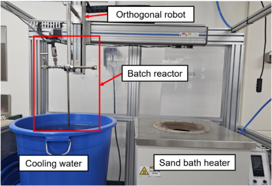
The batch reactor assembly was incorporated into the pyrolysis experimental test rig, which comprised a heater, a cooling water reservoir, and an orthogonal robot, as illustrated in Fig. 1. Heating and cooling of the reactor were achieved by transferring it between the heater and room-temperature cooling water using the orthogonal robotic system. In the present study, a custom-designed sand bath heater was employed, wherein compressed air was used to fluidized alumina sand, thereby providing uniform heating. This configuration enabled rapid fuel conversion at temperatures up to 700°C, allowing for shorter reaction durations than those typically reported in previous batch reactor studies [18,19,20,21] while maintaining high conversion efficiency [25].
2.2 Test fuel and experimental conditions
The test fuel employed was military jet fuel JP-8. Although the exact critical values of the JP-8 fuel used in this study are unknown, we adopted critical pressure and temperature values of 23.4 bar and 410°C, respectively, from the literature [6,10]. To ensure supercritical operation, the initial reaction pressure was set to 30 bar, and the reaction temperature was maintained above 500°C. It should be noted that when heated under conditions above the critical pressure, the liquid fuel transitions into a supercritical state without undergoing a distinct phase change. The detailed experimental conditions are summarized in Table 1. A fixed fuel volume of 2 mL was subjected to reaction temperatures ranging from 525°C to 625°C, in 25°C increments, with reaction durations of 100, 160, and 220 s.
Table 1.
Experimental conditions.
| Parameter | Value |
| Temperature | 525-625°C |
| Initial pressure | 30 bar |
| Reaction time | 100-220 s |
| Fuel volume | 2 mL |
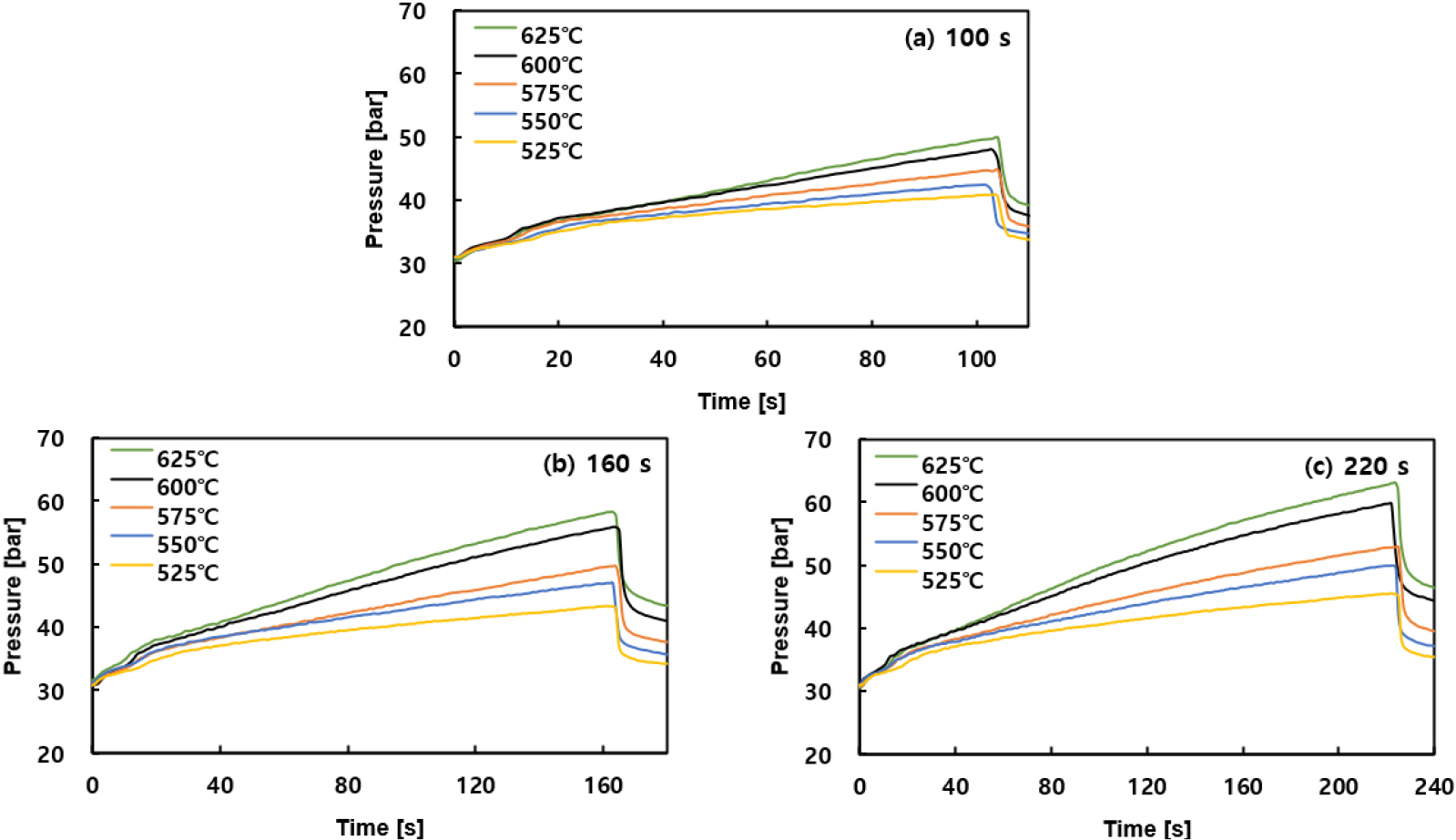
During the experiments, the internal pressure of the reactor was measured using a pressure sensor mounted on the batch reactor. As the reaction progressed, gaseous products were generated, leading to a continuous increase in internal pressure. This behavior is characteristic of experiments employing a constant-volume reactor, and similar trends have been reported in previous studies [18,19,20,21]. The pressure variations under each experimental condition are presented as pressure-time profiles in Fig. 2.
Regarding the internal temperature of the reactor, a previous study conducted by our research group revealed that when a thermocouple was installed, the fuel temperature exhibited a steep rise during the first ~40 s after the onset of reaction, followed by a gradual increase approaching the heater set temperature. However, when a thermocouple was mounted inside the batch reactor, severe coking occurred due to direct contact between the fuel and the thermocouple structure. In addition, the volume occupied by the thermocouple reduced the effective volume of the reactor, thereby causing the internal pressure to rise more significantly than in the absence of a thermocouple. These two factors were found to alter the results of the pyrolysis reactions [25,26]. Consequently, in the present study, no thermocouple was installed for fuel temperature measurement inside the reactor; instead, the progress of the reaction was assessed solely by monitoring the internal pressure variation during the process. The reaction time was counted from the moment the reactor was inserted into the heater, and upon reaching the target duration, the reactor was immediately transferred to the cooling water bath to terminate the reaction.
2.3 Experimental procedures
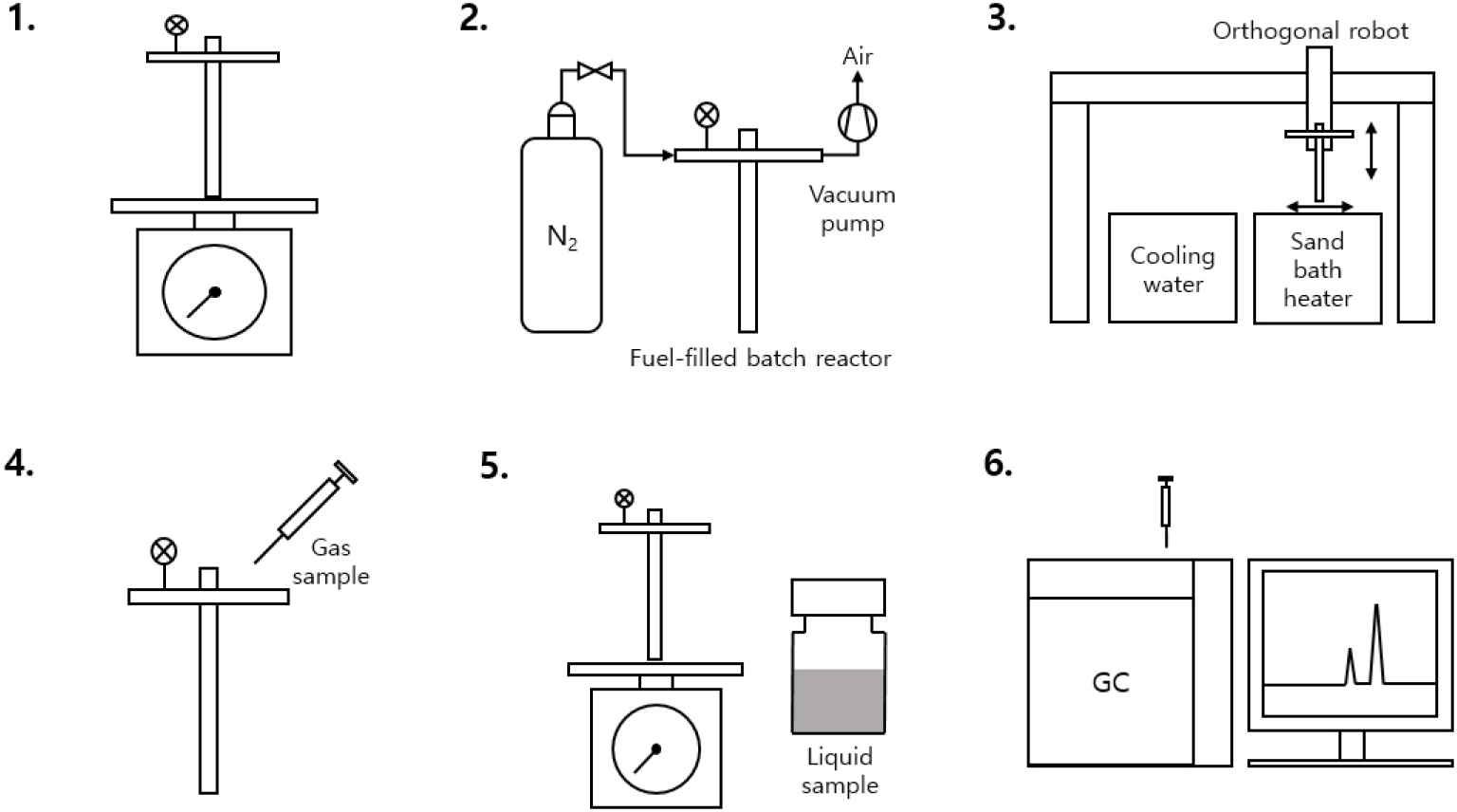
The experimental procedure for the pyrolysis reaction is outlined in Fig. 3. First, the mass of the batch reactor is measured before and after fuel injection to determine the initial mass of the injected fuel (1). Next, a vacuum pump is used to evacuate the reactor, thereby removing residual air, particularly oxygen. Subsequently, high-purity nitrogen (99.999%) is introduced to pressurize the reactor to the desired experimental pressure (2). Once the experimental conditions are established, the reactor is mounted on the orthogonal robot and transferred to the heater for heating. After the prescribed reaction time, the reactor is rapidly quenched by immersion in room-temperature cooling water to immediately terminate the reaction (3). Following cooling, gaseous products are extracted, and any residual gas in the reactor is vented (4). The batch reactor mass is then re-measured, and liquid products are collected (5). Finally, the extracted gaseous and liquid products are analyzed using gas chromatography systems (6).
2.4 Pyrolysis products analyses
Three GC (Gas Chromatography) systems were employed for the analysis of the pyrolysis products. An Agilent 7890/5975 GC-MSD (Gas Chromatography - Mass Selective Detector) system was used for the identification of liquid products and the determination of their relative ratios. Hydrogen quantification was carried out using an iGC7200A GC (DS Science Inc.) equipped with a TCD (Thermal Conductivity Detector). In addition, an Agilent 8860 GC equipped with a FID (Flame Ionization Detector) was utilized for the mass fraction analysis of low-molecular-weight hydrocarbons, which remain in the gas phase at room temperature, as well as for fuel composition analysis before and after the reaction. The detailed operating conditions of the GC systems are provided in Tables 2 and 3.
Table 2.
Analysis conditions of GC-MSD and TCD.
Table 3.
Analysis conditions of GC-FID.
2.5 Analysis methods
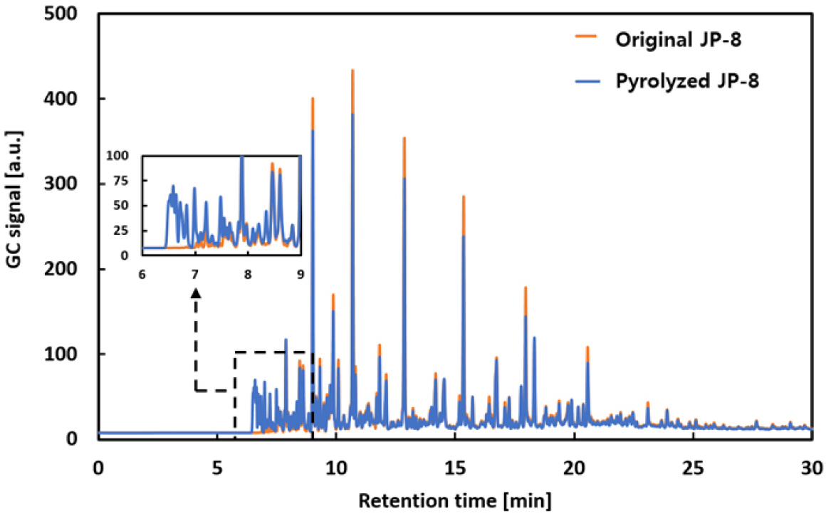
In this study, fuel conversion, gas production rate, and selectivity were selected as the primary indicators for analyzing the results of the pyrolysis experiments. For single-component fuels such as JP-10, a distinct peak is detected in the GC analysis, making it relatively straightforward to calculate fuel conversion based solely on the change in the peak area [25,26]. However, JP-8 is a fuel composed of more than 100 hydrocarbons, and GC analysis produces multiple peaks, making it difficult to apply the same conversion calculation methods used for single-component fuels. As can be seen in Fig. 4, after approximately 7 minutes, peaks are distributed evenly across the entire detection period and often overlap at the same retention times. Consequently, it is impossible to clearly distinguish reactants from products based solely on retention time, or to calculate conversion using the change in area of all peaks. Therefore, in this study, a selection of representative components with large peak areas and distinct changes before and after the reaction was made, and the fuel conversion was calculated using Eq. (1). This analytical approach has been previously validated and confirmed to be effective for determining the conversion of mixed fuels [27]. Meanwhile, the gas production rate was calculated using Eq. (2), and the selectivity, representing the number of moles of a specific product formed per mole of decomposed fuel, was calculated using Eq. (3).
where n is the number of selected peaks, Ai,o and Ai,f represent the peak areas of component i before and after the reaction, respectively, and fi is a correction factor for each component, which was set to 1 in this study. Additionally, mo and ml denote the masses of the fuel before the reaction and the liquid-phase fuel after the reaction, measured using a precision electronic balance. MWi and MWo are the molecular weights of product i and JP-8, respectively. The peak areas of both reactants and products were obtained through GC-FID analysis.
2.6 Uncertainty analysis of pyrolysis experiments
To evaluate the repeatability and measurement uncertainty of the pyrolysis experiments, three replicate tests were conducted under the conditions of 575°C, 30 bar, and 160 s, and the results are summarized in Table 4. The mean and standard deviation of the fuel conversion were 39.46% and 1.98%, respectively, with an uncertainty of ±4.91% at a 95% confidence level based on the student’s t-distribution. The mean and standard deviation of the gas production rate were 12.35% and 1.99%, respectively, and the corresponding uncertainty, calculated using the same method, was ±4.95%.
Meanwhile, the reproducibility of the quantitative analysis of gaseous products was evaluated by injecting the same sample three times, and the GC-FID results for representative peaks are presented in Table 5. The RSD% (Relative Standard Deviation) of the analyzed peak areas ranged from 0.56% to 15.82%, with an average RSD% of 6.46%. The reproducibility of hydrogen quantification was assessed by performing three repeated analyses of the same sample using GC-TCD, and the hydrogen mass, calculated via the calibration curve, is summarized in Table 6. The RSD% of the calculated hydrogen mass ranged from 5.60% to 16.46%, with an average RSD% of 9.09%.
Table 4.
Experimental uncertainty analysis for fuel conversion and gas production rate.
Table 5.
GC-FID repeatability for representative gaseous peaks.
Table 6.
GC-TCD repeatability for hydrogen quantification.
3. Results of Pyrolysis Experiments
3.1 Fuel conversion and gas production rates
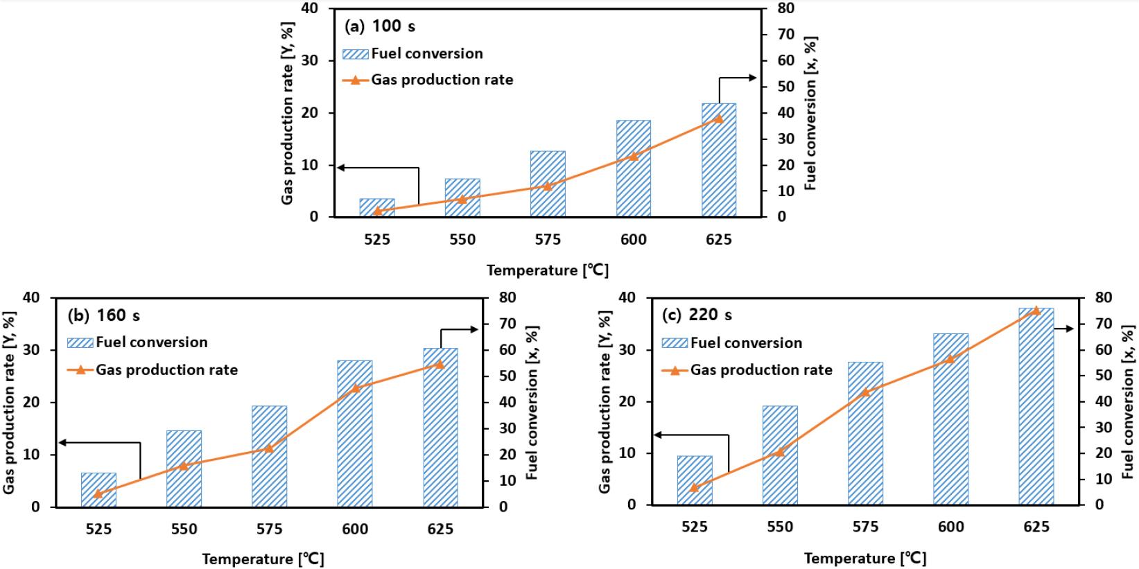
The fuel conversion and gas production rates obtained from the pyrolysis experiments are shown in Fig. 5(a)-(c). The figures present the results of thermal cracking at temperature conditions ranging from 525°C to 625°C in 25°C increments, with reaction times of 100, 160, and 220 seconds, respectively. As shown in the figures, for reaction times of 100 seconds or longer, both fuel conversion and gas yield showed an increasing trend as reaction temperature and time increased. Across all reaction conditions, the fuel conversion varied from approximately 7% to a maximum of 76%, while the gas yield ranged from about 1% to a maximum of 37%.
3.2 Pyrolysis products
In this study, the product distribution data obtained under various reaction temperatures and residence times were analyzed on the basis of fuel conversion. Conversion serves as an indicator of the extent of pyrolysis under different experimental conditions and is an effective parameter for analyzing changes in product composition. For this reason, previous studies have also investigated product distributions as a function of conversion [21]. In particular, considering that the objective of this work is the development of a global PPD reaction model, quantitative analysis of major pyrolysis products with respect to conversion is essential. Accordingly, this section discusses the distribution characteristics of JP-8 pyrolysis products in relation to conversion.
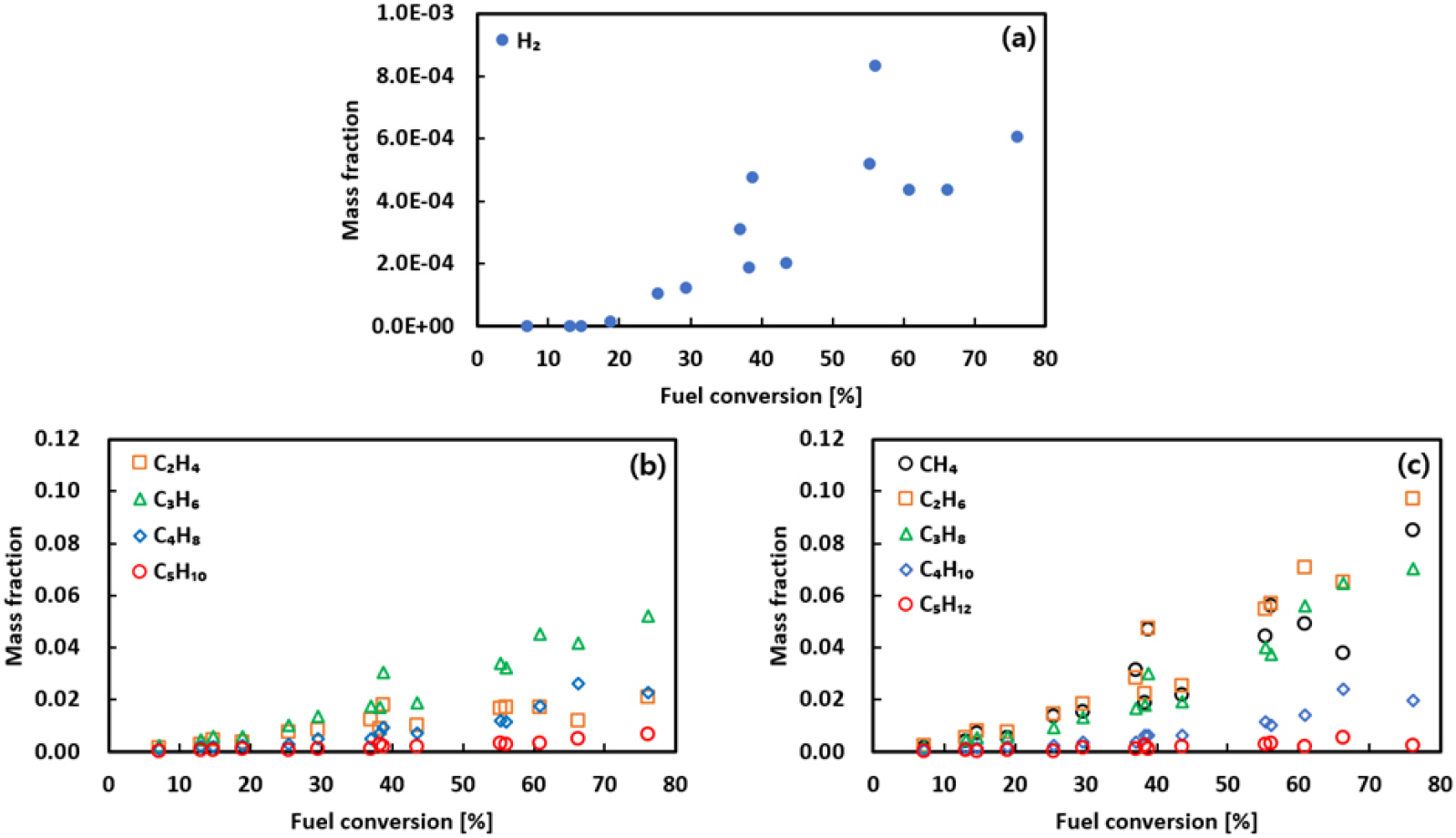
The gaseous products generated from the pyrolysis experiments were analyzed, and their mass fraction distributions as a function of conversion are presented in Fig. 6. Qualitative analysis using standard gases identified the major gaseous products as H2, CH4, C2H4, C2H6, C3H6, C3H8, C4H8, C4H10, C5H10 and C5H12. These species have also been similarly reported in pyrolysis experiments of other aviation fuels [4,15,16]. Furthermore, since the present study aims to develop a pyrolysis reaction model for JP-8, gaseous species with four or more carbon atoms were integrated into representative species such as C4H8 and C4H10, without distinguishing between isomers. Examining the distribution characteristics of the gaseous products, most species exhibited a nearly linear increase in mass fraction up to a conversion of about 30%, followed by a more rapid rise thereafter. Among the alkenes, C3H6 showed the highest mass fraction, while in the alkanes, CH4, C2H6, and C3H8 accounted for a large proportion and overall exhibited higher mass fractions compared to the alkenes. In contrast, C5H10 and C5H12 maintained relatively low mass fractions across the entire conversion range.
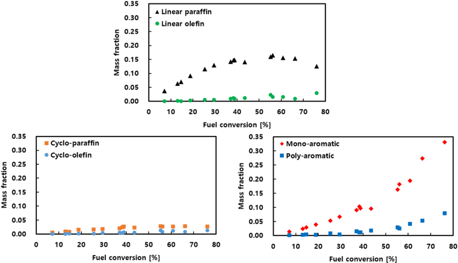
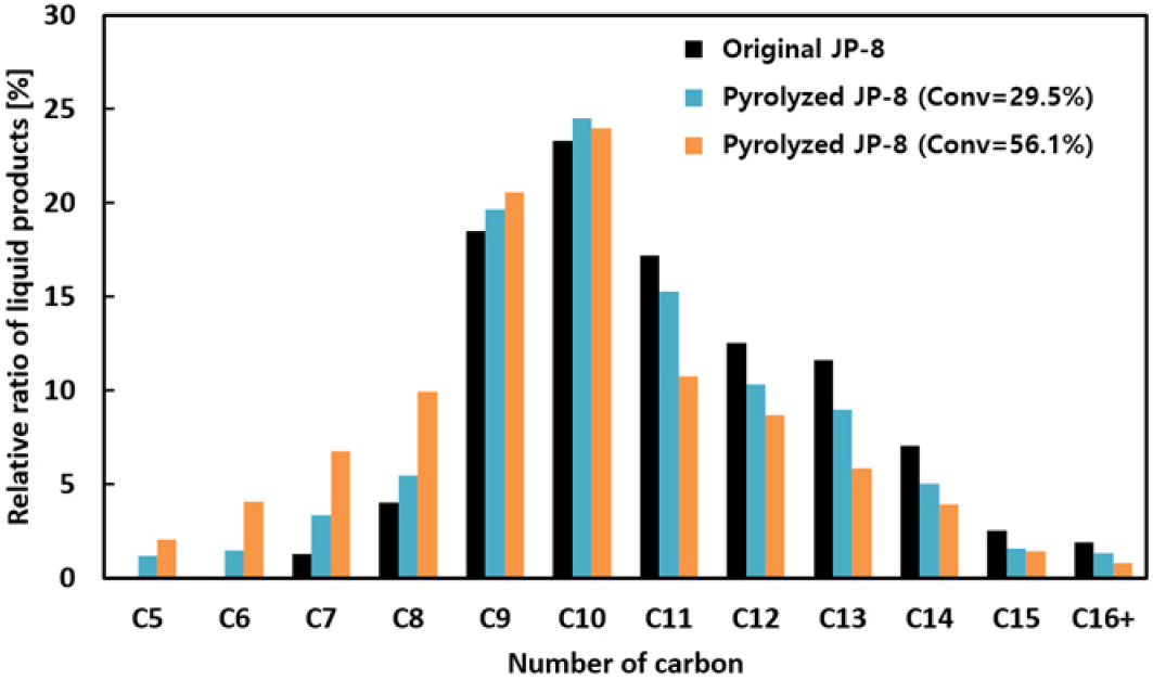
Unlike gaseous products, liquid products were detected as more than 100 different species across the entire conversion range, making it impractical to analyze each component individually. Therefore, in this study, the products were classified into six categories according to their parent molecular structures: linear paraffins, linear olefins, cyclo-paraffins, cyclo-olefins, mono-aromatics, and poly-aromatics. The mass fraction distributions of these groups with respect to conversion are presented in Fig. 7. At conversions below 30%, most liquid products exhibited a nearly linear increase, similar to the gaseous products. In this range, linear paraffins showed the highest mass fraction, followed by mono-aromatics, while the other groups maintained relatively low fractions. In the 30-50% conversion range, the growth rate of linear paraffins gradually slowed, whereas the aromatic species exhibited a pronounced increase. Beyond 50% conversion, the fraction of linear paraffins began to decrease, while the aromatics continued to increase, with mono-aromatics showing the highest mass fraction among them. This trend is associated with the secondary decomposition of linear paraffins into gaseous and low-molecular-weight liquid products, as well as their conversion into aromatic compounds [28,29]. In addition, Fig. 8 presents the carbon number distribution of the decomposition products. As conversion increased, the relative proportion of high-carbon-number species (C11 and above) decreased, while the fraction of low-carbon-number species in the C5-C8 range increased significantly. This clearly demonstrates the characteristic decomposition of the high-molecular-weight compounds originally present in JP-8 fuel into lower-molecular-weight products.
4. Development of global reaction PPD model
4.1 Surrogate model of JP-8
To apply mixed fuels such as JP-8, which consist of various hydrocarbons, to numerical simulations, it is necessary to simplify them into surrogate mixtures that reduce compositional complexity and improve computational efficiency [30]. For this purpose, in the present study, GC-MS analysis of JP-8 was conducted to determine the proportion of each molecular structure group and their average molecular weights, with the results summarized in Table 7. Based on these results, the average chemical formula of JP-8 was calculated as C11.04H21.70, corresponding to a hydrogen-to-carbon ratio (H/C) of approximately 1.97. This value is similar to the H/C ratio of 1.91 reported in the literature for a representative JP-8 composition. Although some variation may arise from differences in detailed fuel formulations, the comparison shows that the analysis results of this study fall within a range consistent with reported literature values [6].
Table 7.
GC-MS analysis results of JP-8 by molecular-structure group.
Based on this analysis, surrogate components were selected for each structural group by choosing compounds with similar molecular structures and average molecular weights. Since linear olefins and poly-aromatics were found in very small proportions, and cyclo-olefins were not detected, these groups were excluded from the surrogate formulation. Ultimately, representative species were assigned to three structural groups: linear paraffins, cyclo-paraffins, and mono-aromatics. Specifically, the dominant linear paraffin group was represented by a mixture of n-decane, n-dodecane, and n-tridecane; the cyclo-paraffins were represented by n-butylcyclohexane; and the mono-aromatics by trimethylbenzene. These surrogate species have also been shown in previous studies to effectively reproduce the thermophysical properties and pyrolysis behavior of aviation fuels similar to JP-8 [4,28], thereby validating the suitability of the surrogate model proposed in this study. Furthermore, to simplify the complexity of fuel composition changes due to pyrolysis, linear-chain compounds with five or more carbons were grouped as C5, cyclic compounds as CC5, and aromatic compounds as CnH2n-6. The representative components and compositions of each group were selected with reference to previous studies [4,28], and the detailed formulation is summarized in Table 8.
Table 8.
Surrogate compounds of JP-8 and cracked products.
4.2 Selectivity analysis
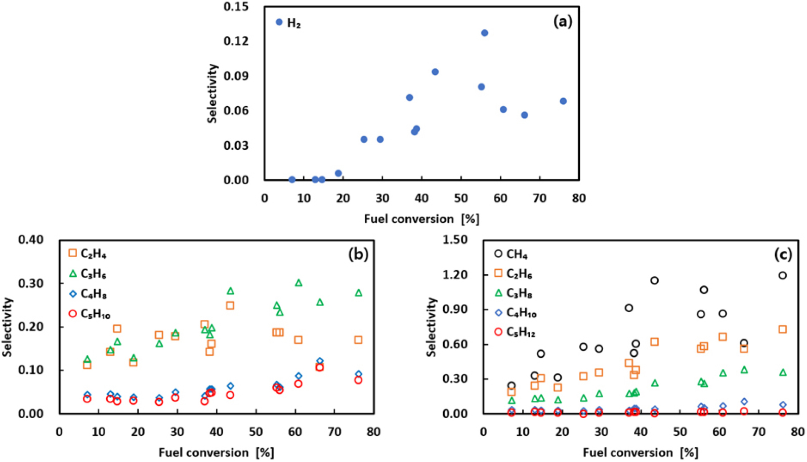
Based on the analysis of pyrolysis products, selectivity analysis was conducted to quantify the relative proportions of the products and to utilize this information in determining the stoichiometric coefficients of the global PPD reaction model. The selectivity of gaseous and grouped liquid products with respect to fuel conversion was summarized and presented in Figs. 9 and 10, respectively. For gaseous products, as shown in Fig. 9, most species except hydrogen exhibited little change or only a gradual increase in selectivity at conversions below 30%. However, beyond 30% conversion, the selectivity of all gaseous products, except C2H4, continued to increase as conversion progressed.
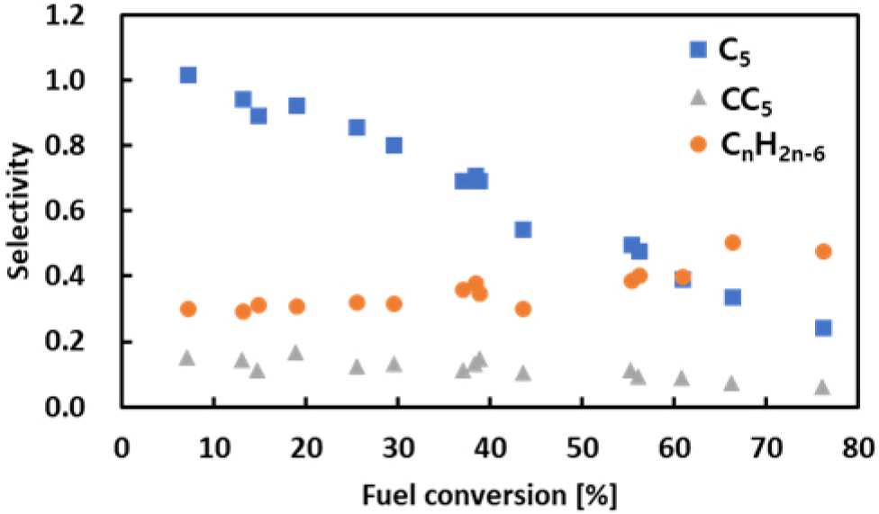
For liquid products, the selectivity variations of the C5, CC5, and CnH2n-6 groups were compared and are shown in Fig. 10. As illustrated, the C5 group exhibited the highest selectivity below 30% conversion, with relatively modest changes, but showed a progressively sharper decline beyond this range. In contrast, the aromatic group (CnH2n-6) maintained nearly constant selectivity at conversions below 30%, then steadily increased with higher conversion, eventually reaching or surpassing the level of the C5 group at conversions above 60%. The CC5 group maintained very low selectivity across the entire conversion range, remaining constant below 30% and showing a slight decrease beyond this point.
From these selectivity distributions, it can be inferred that at conversions below 30%, most products are generated in almost fixed proportions, corresponding to the primary cracking region. When conversion exceeds 30%, however, secondary cracking occurs, in which relatively high-molecular-weight liquid products further decompose into gases and aromatic compounds [16].
4.3 Global one-step reaction model of JP-8
Numerous previous studies have reported global reaction models for alkane hydrocarbons such as n-decane and n-dodecane, as well as kerosene-based mixed fuels [4,12,16,31,32]. In general, the pyrolysis reactions of such fuels can be adequately represented by a global one-step reaction model based on the PPD (Proportional Product Distribution) assumption, which states that the products appear in fixed ratios at low levels of fuel conversion. In particular, Ward et al. [31] reported in their study on pure n-decane that the product distribution remains constant below 20% conversion, but changes beyond this point. Similarly, the studies of Jiang et al. [4] and Li et al. [16] on mixed fuels confirmed that product proportions remain nearly constant up to 20% and 30% conversion, respectively.
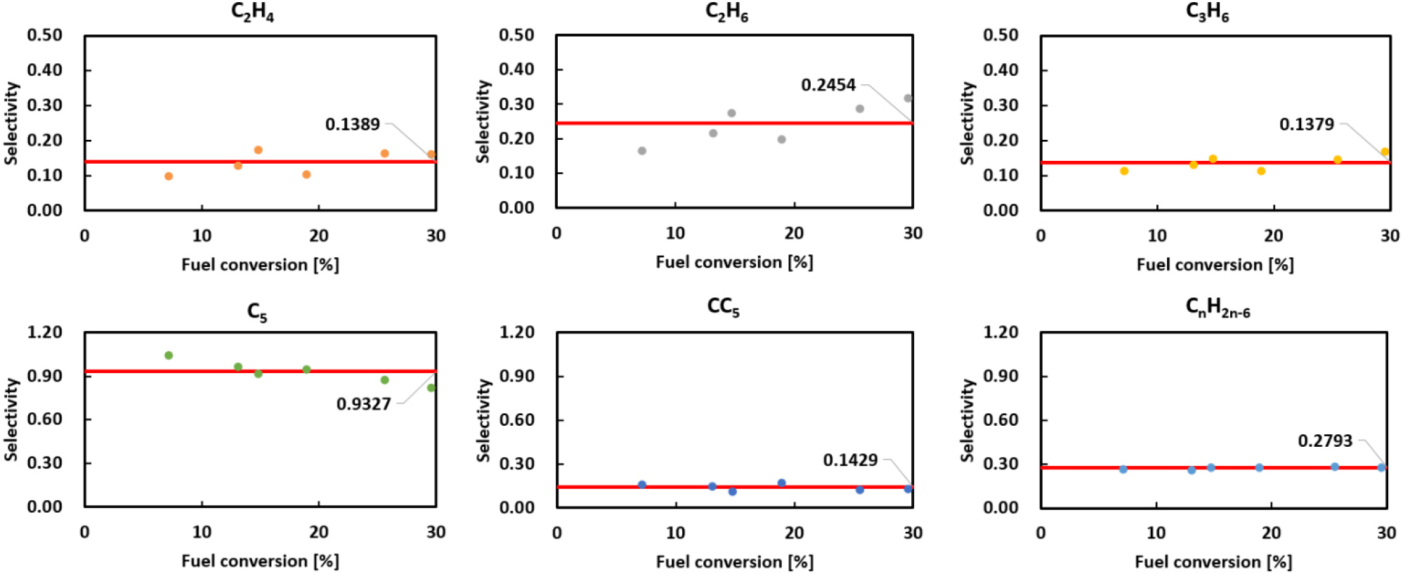
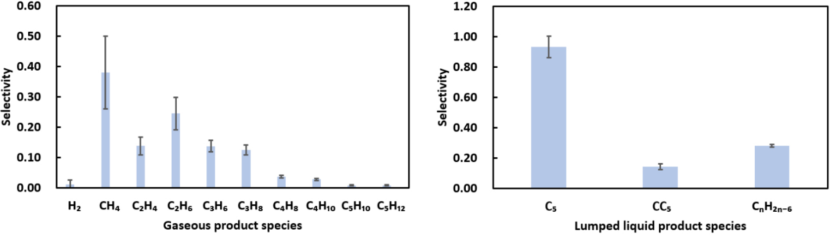
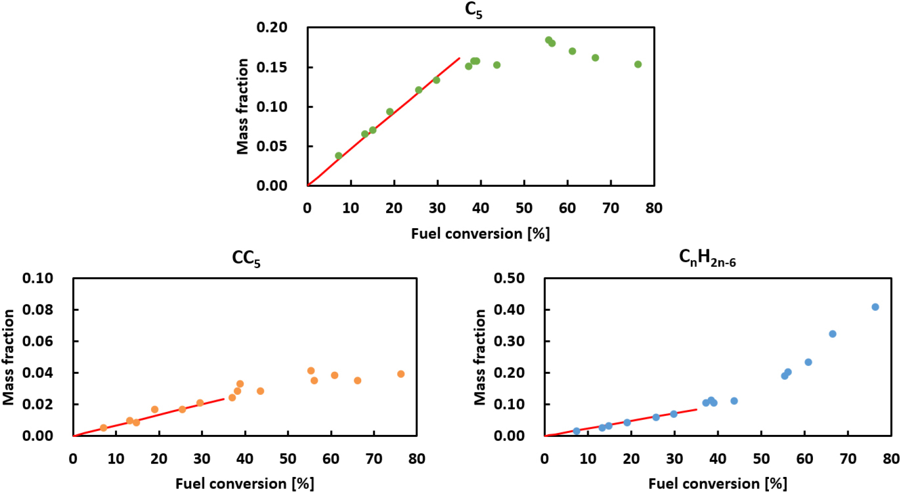
This trend was also observed in the selectivity analysis conducted in Section 4.2 of the present study. Based on this finding, a global one-step reaction model applying the PPD assumption was developed for JP-8 under conditions where the fuel conversion is below 30%. To construct the model, the average selectivity of each product was calculated within this conversion range. The analysis results for the major products are shown in Fig. 11, while the average values and standard deviations for all products are presented in Fig. 12. Using these results, stoichiometric coefficients for each product were determined and then fine-tuned to satisfy mass conservation, thereby formulating the global one-step reaction PPD model for JP-8. The final reaction model is presented in Eq. (4), and is valid for conversions up to 30%. Beyond this threshold, the accuracy of predicting pyrolysis product distributions may decrease.
5. Model Implementation in Numerical Simulation
5.1 Geometry and mesh generation
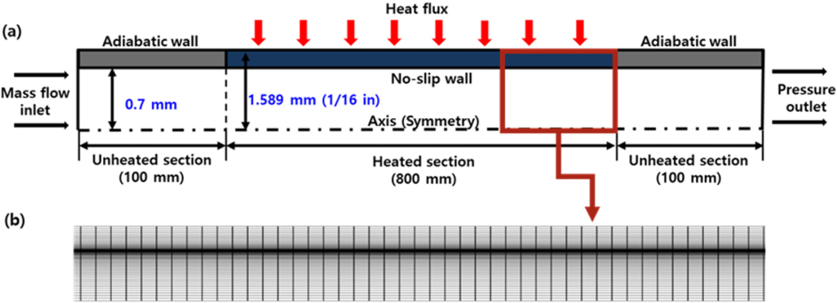
In this chapter, CFD (Computational Fluid Dynamics) simulations were conducted to evaluate the predictive performance of the global reaction model presented earlier for regenerative-cooled microchannels. The geometry used for the analysis was modeled as a two-dimensional axisymmetric tube, with an inner diameter of 1.4 mm and a wall thickness of 0.889 mm. Of the total 1000 mm length, the inlet and outlet sections, each 100 mm long, were treated as adiabatic, while the central 800 mm section was defined as a heated region with a constant heat flux.
A structured mesh was employed, and the y⁺ value was maintained below 5 to ensure accurate resolution of the wall boundary layer. For mesh independence verification, the total number of mesh elements was varied among 200,000, 375,000, 750,000, 1,000,000, and 1,500,000, and it was confirmed that the results converged at 750,000 elements or more. Accordingly, the final mesh consisted of 750,000 elements (10,000 × 75), and the computational domain along with the generated mesh is shown in Fig. 13.
5.2 Simulation setup
The numerical simulations were performed using ANSYS CFD Fluent 2022R2, applying a pressure-based steady RANS solver. The turbulence model employed was the standard k-ε with enhanced wall treatment based on the comparative study by Xu et al. [33,34], and the chemical reaction model was based on finite-rate/eddy dissipation. All other numerical methods were set in accordance with the previous study by Lee et al. [34,35]. Thermophysical properties of the fuel and products, including density, constant pressure specific heat, viscosity, and thermal conductivity, were obtained from the NIST SUPERTRAPP (STRAPP) database under a constant pressure of 3 MPa, and then approximated using polynomial fits for application in the numerical simulations [34,35,36]. For mixtures such as the JP-8 surrogate, the compound function was utilized to derive these properties.
In the numerical analysis of this study, we directly used the kinetic parameter values proposed by Jiang et al. [4] for HF-1 aviation fuel, which has composition and physical properties similar to those of JP-8. Accordingly, the activation energy and pre-exponential factor were set to 217.9 kJ/mol and 2.87 × 10¹⁴ s-1, respectively. Meanwhile, in an attempt to derive the kinetic parameters specific to the JP-8 fuel used in this study, we estimated the coefficients based on the pyrolysis results from the batch reactor experiments; however, under the experimental conditions of this study, the derived values were found to be excessively lower than those reported in previous studies. Therefore, in future work, we plan to use a microchannel flow-reactor system to conduct JP-8 pyrolysis experiments under conditions similar to those of an actual regenerative cooling channel and, on this basis, derive kinetic parameters unique to JP-8 fuel. The simulation conditions were set such that the fuel conversion at the channel exit reached approximately 30%, and the detailed simulation parameters are summarized in Table 9.
Table 9.
Boundary and operating conditions used in simulation.
| Parameter | Value |
| Working fluid | JP-8 surrogate |
| Inlet temperature | 300 K |
| Operating pressure | 3 MPa |
| Heat flux | 170 kW/m2 |
| Mass flow rate | 0.7 g/s |
5.3 Results and discussion
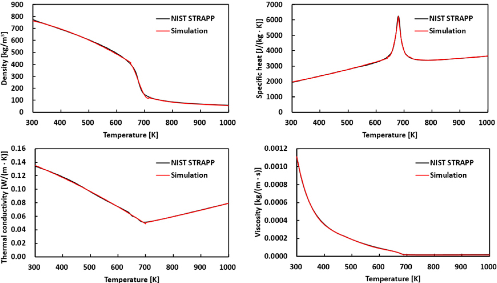
First, to verify the accuracy of property implementation, a numerical simulation was conducted for the JP-8 surrogate under heating conditions only, excluding the pyrolysis reactions. The thermophysical properties obtained from the simulation as a function of temperature were compared with the NIST STRAPP data. As shown in Fig. 14, density, constant pressure specific heat, thermal conductivity, and viscosity showed good agreement across the entire temperature range, thereby validating the reliability of the property acquisition and implementation method used in this study.
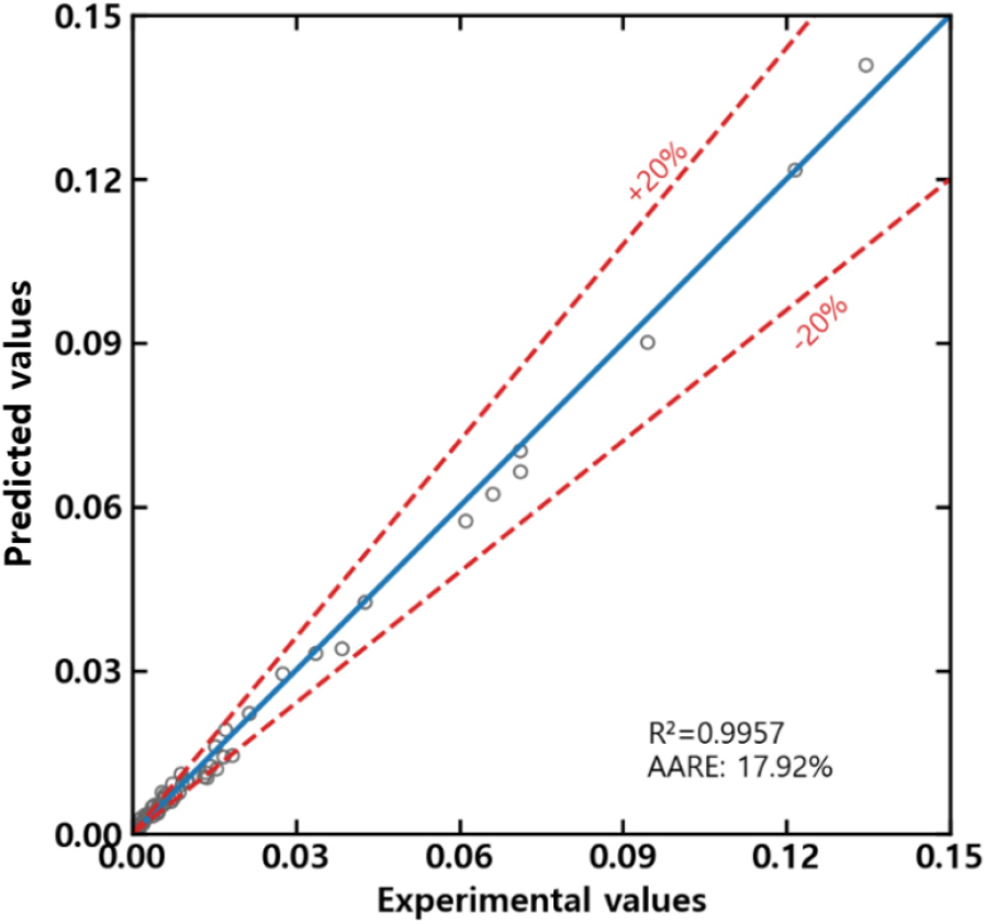
Based on this validation, the developed pyrolysis model was applied to the regenerative-cooled microchannel to simulate pyrolysis reactions. The resulting mass fractions of gaseous and liquid products, presented in Figs. 15 and 16, closely matched the experimental results, accurately reproducing the average trends observed in the experiments. Furthermore, quantitative evaluation of the error characteristics through correlation between predicted and experimental values showed that most data points fell within a ±20% error range, as illustrated in Fig. 17. Therefore, the pyrolysis model developed in this study quantitatively reflects the experimental results and demonstrates sufficient predictive reliability for use in engineering analyses and design purposes.

6. Summary and Conclusion
In this study, the endothermic decomposition characteristics of JP-8, a representative kerosene-based aviation fuel, were analyzed using a batch reactor experimental setup. The experiments were conducted at a pressure of 3 MPa and temperatures of 525-625°C, with residence times ranging from 100 to 220 s, during which the maximum fuel conversion reached approximately 76%, and the gas yield was around 37%. Analysis of the products revealed that the major gaseous species were H2, CH4, C2H4, C2H6, C3H6, and C3H8, with most gas mass fractions increasing as fuel conversion progressed. In contrast, over 100 compounds were detected in the liquid products, which were categorized and analyzed based on their parent molecular structures. The results showed that linear paraffins dominated in the early stages of the reaction, but their proportion decreased with increasing conversion, while aromatic species exhibited a pronounced increase.
Next, GC-MS analysis was used to determine the average chemical formula of JP-8 as C11.04H21.70, and a surrogate model was developed based on the major structural groups. Using this surrogate, a global one-step reaction model for JP-8 was developed under the PPD (Proportional Product Distribution) assumption, which assumes that product selectivity remains constant at conversions below 30%. When applied to a regenerative-cooled channel configuration in numerical simulations, the model accurately predicted the mass fraction changes of gaseous and liquid products with conversion, with most predicted values falling within ±20% of the experimental results.
This study provides critical information for understanding the pyrolysis characteristics of JP-8 by presenting product composition changes over a wide range of fuel conversions under supercritical conditions. The proposed pyrolysis reaction model will undergo further validation by comparing CFD simulation results with experimental data from the microchannel flow-reactor facility operated by the authors’ research group. Additionally, by incorporating data accumulated from both batch and flow reactors, the model will be refined and extended into a multi-step model capable of application at higher conversion levels. Future work also aims to perform experiments at elevated pressures to develop a pyrolysis reaction model that is reliable across a broad range of operating conditions. Overall, the model developed in this study can be used to predict fuel flow and endothermic decomposition behavior within regenerative-cooled channels and is expected to serve as a valuable tool for the design and analysis of regenerative cooling systems for hypersonic vehicles.
