

1. Introduction
2. Numerical Procedure
2.1 Geometrical model
2.2 Governing equations and turbulence model
2.3 Grid independence
2.4 Parameters for flow analysis
2.5 Validation for flow analysis
3. Results and Discussion
3.1 Pressure and flow distributions
3.2 Effects of the number of outlet branches
3.3 Effects of inlet Reynolds number
3.4 Effects of different inlet positions
4. Conclusion
1. Introduction
The manifold system has a specific feature in which increases one flow passage is branched to the several flow passages. Its flow control capability is being used in various fields, including water treatment [1], polymer processing [2], chemistry [3], chemical reactor [4], fuel cell [5], biomedicine [6], agriculture [7], environmental engineering [8], and heat exchanger [9,10]. Based on the flow type from inlet towards outlet, the manifold system is generally based on four types of dividing flow, combining flow, reverse flow of U-type, and parallel flow of Z-type [11,14,13]. In the dividing manifold, a single main stream is divided into several smaller streams, whereas several smaller streams of the combining manifold are gathered in single main stream. And the structures of U-type and Z-type are the form in which dividing and combining flows are combined. The main stream is divided and then it is again combined. The difference of two types is only the outflow direction. Therefore, based on these structural features, the dividing manifold needs to be studied in terms of distributing flow rates and the results of such studies are meaningful for manifold design.
In dividing manifolds, a large fluid stream from the inlet is distributed to multiple branching outlets and the main flow rate is reduced while passing through each outlet. Such flow branching causes the reduction of the momentum and flow rate. In this case, since the flow distribution is mainly determined by the momentum loss, it is described by the momentum dominated condition [14]. Also, when the main flow is discharged to the outlets, T-junction flows with the 90° turning movement are formed near each outlet. These two characteristics are factors for rising pressure (>0). However, the pressure is generally reduced by the frictional force in the direction of flow development. When the >0 condition is dominated, the flow distribution is characterized by the friction dominated condition. Therefore, these changes of momentum and friction force can produce differently the linear pressure distribution along the main flow direction. The increasing and decreasing tendency of pressure is the main cause of nonuniform outflows called flow maldistribution. The flow maldistribution has a serious impact for the performance of heat or mass transfer in various applications. Therefore, many studies are being conducted to reduce such flow maldistribution. To get a uniform mass flow through each branches, a proper balance between friction and momentum is required. However, based on the basic configuration of dividing manifold, it is difficult to get the uniform flow rate near each outlets. Based on a one-dimensional method, Acrivos et al. [15] showed the pressure fall due to wall friction and the pressure rise. The pressure rise of the flowing type and the pressure fall for the sucking type are obtained depending on the flow direction at the branching outlet. From their results, we understand that factors affecting pressure and momentum should be carefully examined to obtain uniform flows at outlets. From a theoretical flow model, the pressure gradient is described by a second order nonlinear ordinary differential equation. The pressure gradient can be changed by the flow deceleration or acceleration. From a literature survey, such flow changes are strongly related to the manifold configuration. According to Mueller and Chiou [16], main reasons of flow maldistribution are the design of headers and inlet ducts influencing the flow distribution. When the large vortex is formed near the inlet, the pressure increases sharply. Therefore, the simple configuration of dividing manifold is difficult to obtain a uniform distribution of outflow rates.
Up to now, many studies have been conducted to improve these factors. Zhengqing and Tongmo [17] studied analytical solutions of pressure and velocity in the distributing and combining headers of manifold systems. They showed that the static pressure and velocity are closely linked to the header type. Also, Gandhi et al. [18] investigated numerically the effects of geometrical parameters such as the tube pitch, header diameter, tube diameter, number of tubes, inlet or outlet pipe diameter in manifolds of dividing, combining, Z-type, and U-type. They observed that the relative location and arrangement of the tubes for the inlet or outlet pipe are important for the flow and pressure distribution in the manifold systems. Bajura et al. [19] proposed an analytical model for the flow distribution in manifolds and showed experimental results of parallel and reverse type manifolds. They presented the flow and pressure variations for different lateral and header area ratios. In order to prevent the formation of vortices and dead zones inside a dividing manifold header, the modified header design was investigated by Wen et al. [20]. The flow maldistribution was improved by the configuration with punched baffle. For laminar parallel manifolds to get uniform flow distribution, Tong et al. [21] investigated the best condition of geometrical variables such as header cross-section area, channel diameter, and tapering of the header cross-section. Zhang et al. [22] explored the effects of the inlet Reynolds number, area ratio of inlet and outlet pipes, pipe pitch, height of convex head, and number of outlets on flow uniformity and pressure drop in the dividing manifold system with parallel pipe arrays. They proposed that specific area ratio and pipe pitch are good for flow uniformity and pressure drop. Therefore, the flow maldistribution in the dividing type is mainly caused by the specific configuration. Many studies [16,21,22] have been conducted for the influence of geometric parameters on the flow distribution of dividing, combining, Z-type and U-type manifolds. However, although the combining and arranging method of inlet, outlet, and branch pipes is another important factor for flow distributions, there has been a lack of research on the structural layout of dividing manifolds.
According to Ghani and Sidik [23], the bifurcation type manifold has an advantage for keeping the flow distribution. But, its design and manufacture are complex, because the structure is based on the branched channels of the tree type. When the channel is branched, the flow development is affected by the blockage and turning effect. Therefore, the pressure gradient is severely altered by many flow changes at inlets and outlets of branched channels. Considering this feature, the bifurcation type manifold is suitable for the high flow rate. From a closer inspection of previous studies [23], the bifurcation type manifold achieves the flow uniformity by reducing the pressure difference at each outlet through the channel branching process. The port blockage and the inlet position change induce different flows in the header and inlet of each branch. Therefore, the layout of inlet and outlets is another factor to get a good manifold. However, the effect of the layout on flow uniformity has been studied only to a limited extent.
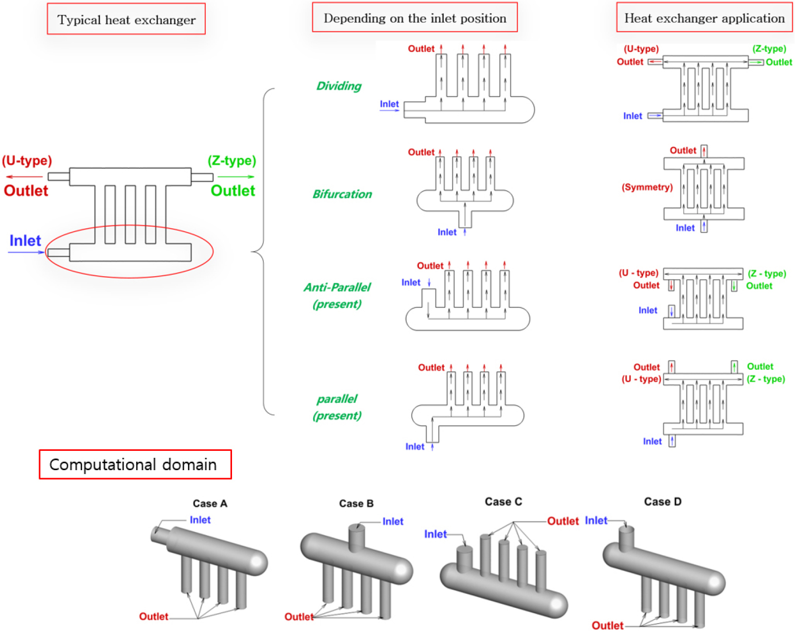
To examine the effects of the inlet position change on the dividing manifold flow, four different manifolds are selected as types of lateral inlet (Case A), central inlet (Case B), anti-parallel of inlet and outlet (Case C), parallel of inlet and outlet (Case D). The dividing and bifurcation types are components of a conventional heat exchanger. From geometric characteristics of the bifurcation type manifold, two types of anti-parallel and parallel of inlet and outlet are devised. Fig. 1 shows a typical heat exchanger and four type manifolds depending on the inlet position. All manifolds can be a component of parallel-flow heat exchangers. Among the different causes of the nonuniform outflow, vortical motions near the header inlet and the pressure drop in the manifold header are important factors. In order to find the best manifold, these two factors should be related to the manifold configuration. In this study, several parameters of the inlet Reynolds number, the number of outlet branches, and the inlet position are considered. From the results, the layout advantageous for uniform outflows is proposed and the feature of the pressure drop is discussed. That is, when friction and momentum effects are ideally balanced, the mass flow rates through manifold branches are equal. The related flow structures are examined in terms of manifold layout.
2. Numerical Procedure
2.1 Geometrical model
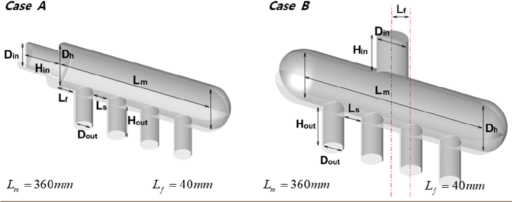
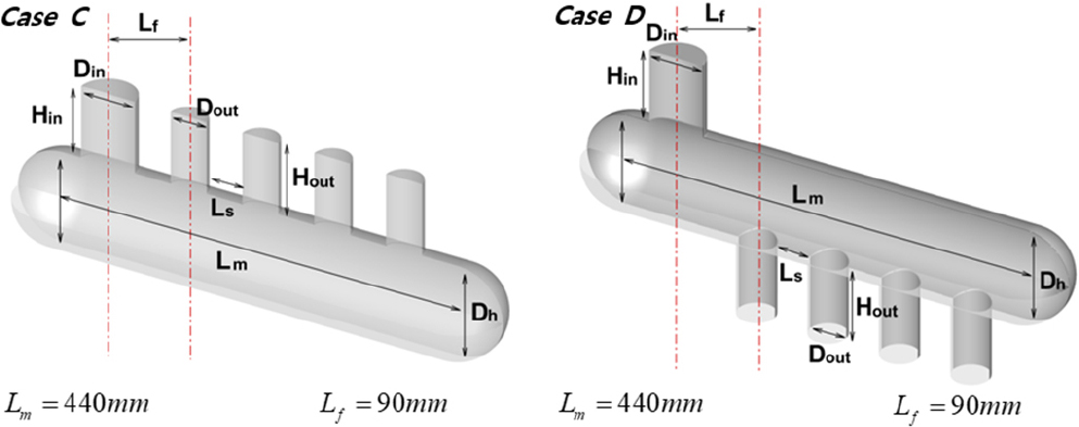
For dividing manifolds with different inlet and outlet positions, four types are explored. Case A is the dividing manifold with lateral inlet and Case B is the central inlet manifold. Based on these two types, the inlet position is newly changed. Case C has anti-parallel flows of inlet and outlet, and Case D has the inlet parallel to outflows. For dividing manifolds, the flow uniformity is improved with decreasing the outlet diameter. Therefore, if the outlet diameter is too small, the geometrical effects are difficult to differentiate. Based on this, the ratio of the inlet diameter to the outlet diameter is selected as 1.5. The geometrical details are summarized in Table 1.
Table 1.
Geometric conditions.
2.2 Governing equations and turbulence model
For three-dimensional incompressible flows, the governing equations of continuity and momentum can be expressed as follows (Eq. (1), (2)).
where, 𝜌, P, , 𝜇, and are density, pressure, velocity, viscosity, and Reynolds stress, respectively. The fluid property is selected as air of 𝜌 = 1.225 kg/m3 and 𝜇 = 1.7894 × 10⁻⁵ kg/m-s.
To describe turbulent flows, the realizable model with the enhanced wall treatment is applied (Eq. (3), (4)).
Here, , 𝜀, , , , and are turbulent kinetic energy, turbulent dissipation rate, turbulent viscosity, generation of turbulent kinetic energy, turbulent Prandtl number for and 𝜀, respectively. Model constants are set : =0.09, =1.44, =1.92, =1.0, =1.3.
The constant velocity condition is applied for the inlet boundary and the pressure outlet boundary is used. In Fig. 1, the positions of inlet and outlet are represented. Then, the Reynolds numbers based on the inlet tube diameter of ReD = 10000, 50000, 100000 are selected to check the Reynolds number dependency. The corresponding velocity is 2.43 m/s~24.35 m/s. The governing equations are solved by the pressure-based SIMPLE algorithm of FLUENT 18.0 [24]. The second-order upwind scheme is selected for the convection terms in all transport equations. The convergence criterion is chosen by the residuals being less than 10-6.
2.3 Grid independence
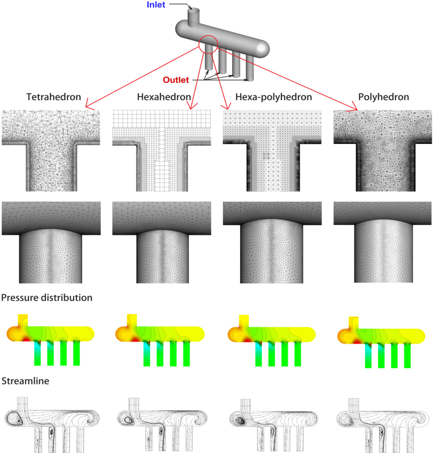
Before proceeding further, the grid types with the basic element of tetrahedron, hexahedron, hexa-polyhedron, and polyhedron are tested in Fig. 2. The internal mesh element consists of tetrahedral, pyramid, hexahedral, and polyhedral elements. To apply the near wall modeling of turbulence equations, the first points from the wall are maintained at y+ < 1. Here, y+ is the non-dimensional normal lengths. After the converged solution is obtained, the grid spacings are modified to meet the y+ < 1 condition. For all grid type, the grid spacing is given for Δx/Dh = 0.1~5, Δy/Dh = 0.1~15, and Δz/Dh = 0.1~10. In that condition, the grid points are about 2.4 million for the polyhedral mesh and 7 million for the other meshes. For different grid types, pressure distributions and streamlines on the center plane of the manifold header are plotted. Despite differences in the number of grids, the results remain highly similar. When the grid number is properly maintained, all four grid types can be utilized. For further calculations, the polyhedral element grid type is selected. To test the adequacy of the grid resolution for further computations, six grid sets of 417000 (i = 1), 842000 (i = 2), 1280000 (i = 3), 1810000 (i = 4), 2390000 (i = 5), and 4970000 (i = 6) control volumes (CVs) are selected. The grid points are clustered near the walls. For all grid resolutions, the first grid point from the wall is nearly maintained at y+ < 1. In a manifold, the distribution of the pressure gradient is important to get a uniform mass flow through each branches. The Euler number is generally used to express the difference of local pressure to inlet pressure (Eq. (5)).
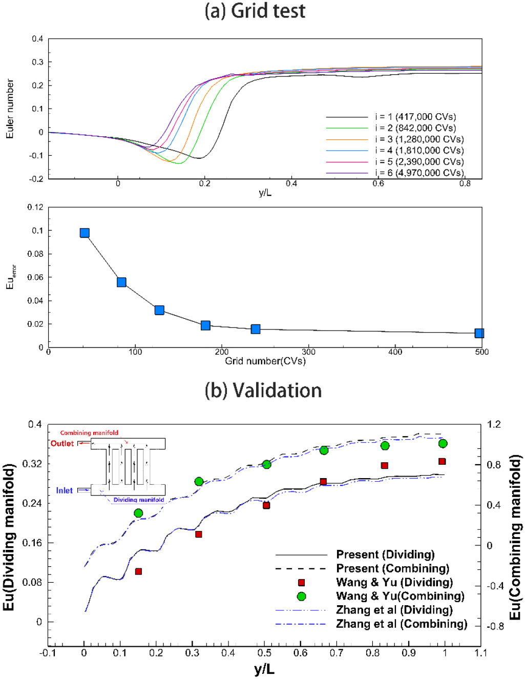
where Px, P0, 𝜌 and U0 are local pressure, inlet pressure, density, and averaged velocity at inlet, respectively. As Eu decreases, it represents the pressure recovery due to the momentum loss. In Fig. 3, the distribution of Eu along the centerline of the manifold head and the relative error of Eu are plotted for six grid resolutions. Here, the relative error is obtained by . As the grid resolution increases, the position of the minimum Eu is moved from y/L = 0.2 to y/L = 0.08 and Euerror is gradually decreased. If the grid resolution is finer than the I = 4 case, Euerror is obtained within 1.5%. The final resolution is determined based on the I = 5 case.
2.4 Parameters for flow analysis
To evaluate the flow maldistribution of a manifold, the difference between the flow rates at each outlet should be analyzed. The following parameter is the maximum difference between the outlet flow rates and it represents the maximum non-uniformity (MNU) of the outlet flow rates for a manifold (Eq. (6)).
where Qmax, Qmin, and Qmean are the maximum, minimum, and mean of the outlet flow rates, respectively. If the uniform outflows are ideally obtained, the MNU value becomes zero. Therefore, this parameter is proper to compare and evaluate the manifold systems. To show the outflow dispersion of each outlet, the non-uniformity coefficient of flow distribution (NUCFD) is defined by Eq. (7)
where Qi is the mass flow rate of the i-th outlet branch and n is the number of outlet branches.
2.5 Validation for flow analysis
The present numerical procedure is applied for the U-type manifold. Fig. 3 shows the Eu distributions for the dividing and combining parts of the U-type manifold. The experimental data [25] and the CFD (Computational Fluid Dynamics) modeling [22] are compared to the present results. According to the experimental and numerical conditions, the flow rates of 6.4 l/min are applied. In a manifold system, the pressure distribution is a critical factor to get the proper flow distribution. The large pressure drop and recovery is related to the momentum change. The numerical results are in good agreement with the experiment in the combining part rather than the dividing part. Although there is a slight discrepancy, the present results are consistent with the other results.
3. Results and Discussion
3.1 Pressure and flow distributions
For different manifolds, the basic features of the flow structure need to be reviewed to seek an optimum manifold. For Re = 10000, Fig. 4 shows three-dimensional pathlines and pressure distributions at the center plane. Depending on the inlet position, three-dimensional vortices are differently developed. Because of that difference, the pressure variation is significantly changed. For Case A, the inlet flow gradually diminishes from the first outlet. The pressure decreases near the first outlet and then increases again. The region of low pressure is concentrated near the first outlet. It can make the enhanced mass flow rate at the first outlet. The large vortex is positioned at the top left corner of the header region and local vortices are formed near the inner wall of each branch tube. But the vortices in the branch tube are gradually disappeared for downstream branches. In the manifold of Case A, it is understood that the excessive pressure recovery and the vortices in the branch tube are important features to determine the outflow distributions.
For Case B, the representative flow structure of the bifurcation type manifold is observed. The inlet flow impinges on the bottom plane of the header region. The vortical regions are weakly formed in the both regions of the header. The high pressure is generated at the bottom surface of the header. As can be seen, the pressure distribution of the header region is more uniform than Case A.
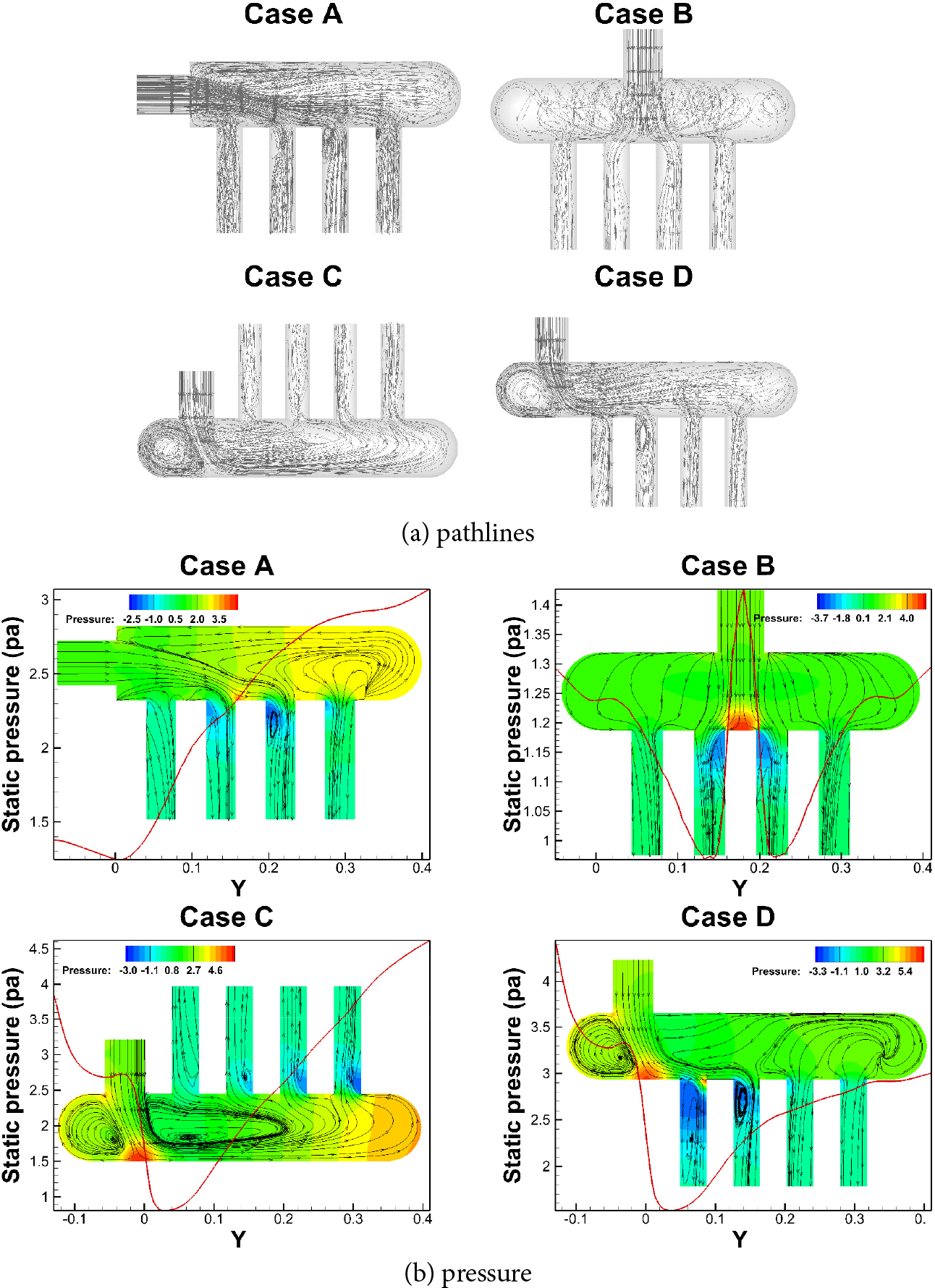
The flow structure is symmetric. As it moves away from inlet, the pressure increases due to the reduction of streamwise momentum. The pressure recovery depends on the development of vortical motions in the upper part of the header and it is not severe. In this type manifold, the pressure drop is dominant near the center branches. For Case C, the impingement of inlet flow is similar to Case B, but the outflow direction is reversed to the inflow direction. The flow structure is similarly asymmetric to Case A. The high pressure region is formed to the side of the header. Due to the difference of momentum, two vortical regions are generated. These vortices interfere with the increased mass flow rate at the first outlet unlike Case A. As a result, the pressure in the header region is recovered to the inlet pressure. For Case D, the pressure is increased at the left bottom of the header. The first branch is close to the high pressure area and its situation is similar to the third branch. Since the outflow direction is parallel to the inflow direction, the flow resistance is not greater than Case A and Case C. The pressure recovery depends on the development of vortical motions in the upper part of the header. From the above results, we understand that the arrangement type of an inlet and outlets can change the vortical flows related to the flow distribution in a manifold.
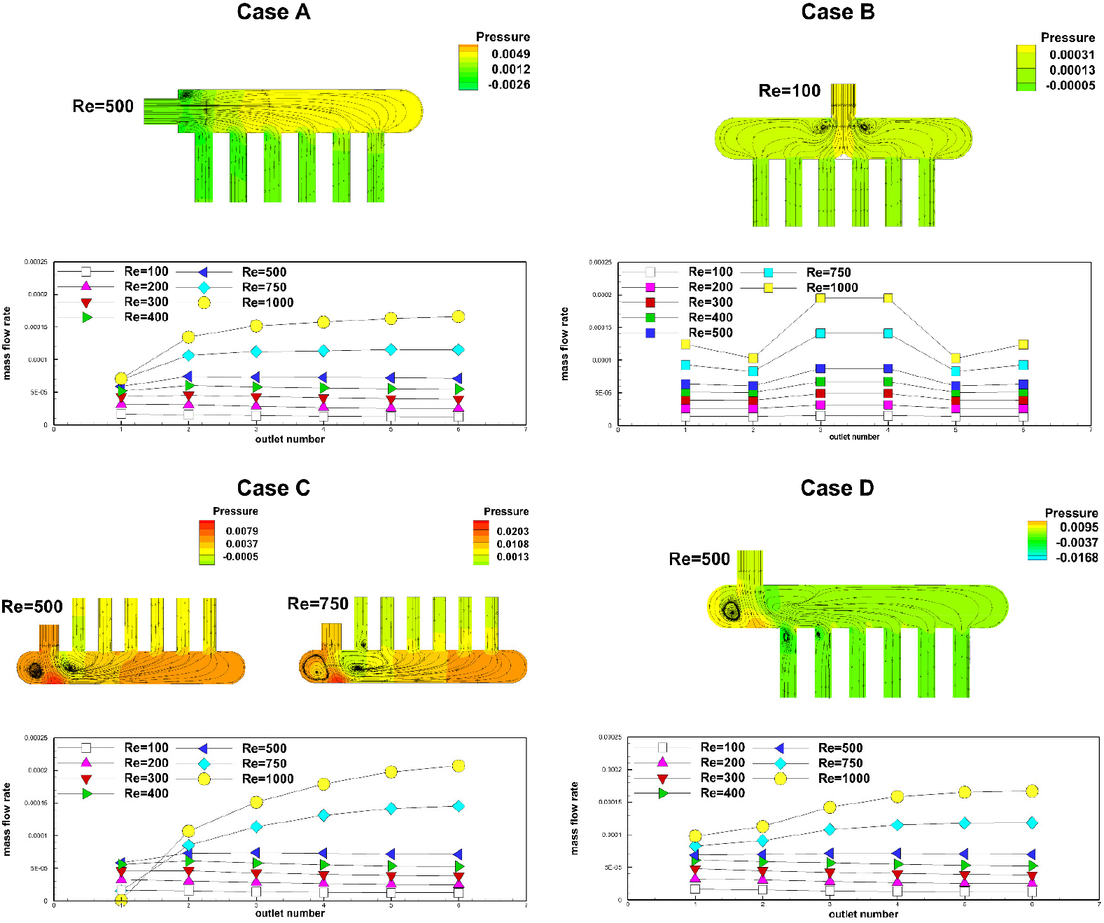
As Re increases, the manifold usually has an equilibrium condition of friction and momentum forces. Fig. 5 shows the outflow distributions of outlet branches for different Re. The streamlines and pressure contours near the equilibrium condition are plotted. As can be seen, the distribution of the mass flow rates shows a significant difference depending on the manifold shape. When the frictional force is dominant, the outflow rate decreases as the outlet position becomes distant from the inlet. This feature is found for small Re cases of four type manifolds. As Re increases, the friction dominant pattern is weakened and the flow is dominated by the momentum. The mass flow rate at the faraway outlet branch increases gradually. As a result, an equilibrium state is obtained. For that condition, the outflow distribution is nearly uniform. However, the mass flow rates at the center branches of Case B is increased with increasing Re. Accordingly, the low Re case shows the most uniform. Except for Case B, the equilibrium state is observed for three type of manifolds at Re = 500~600. The velocity fields inside the outlet branch are nearly parallel to the walls of outlet branch. However, the equilibrium state is different from the conventional heat exchanger operating condition. Therefore, for high Re conditions, it is necessary to understand and reduce the factors of flow maldistribution.
3.2 Effects of the number of outlet branches
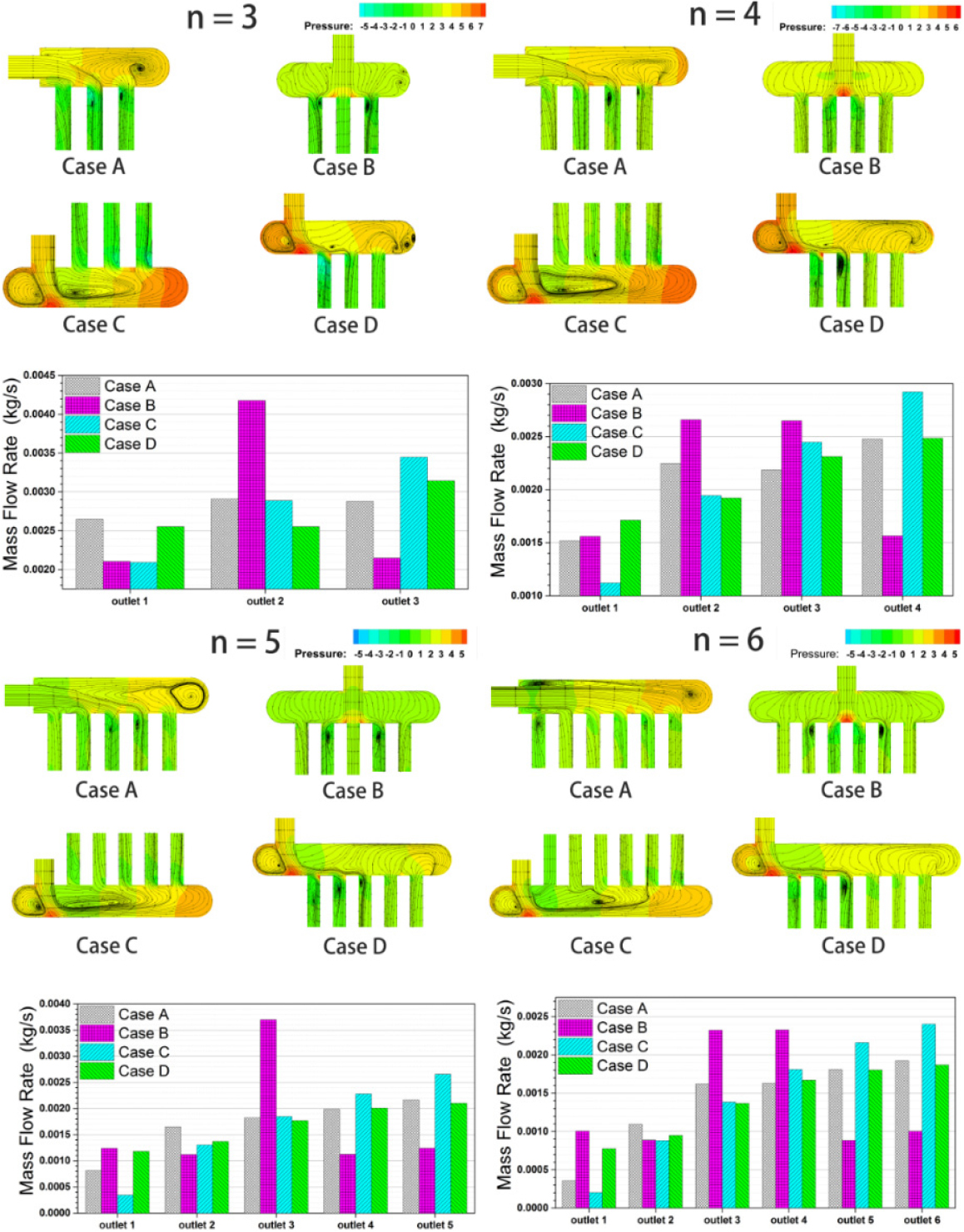
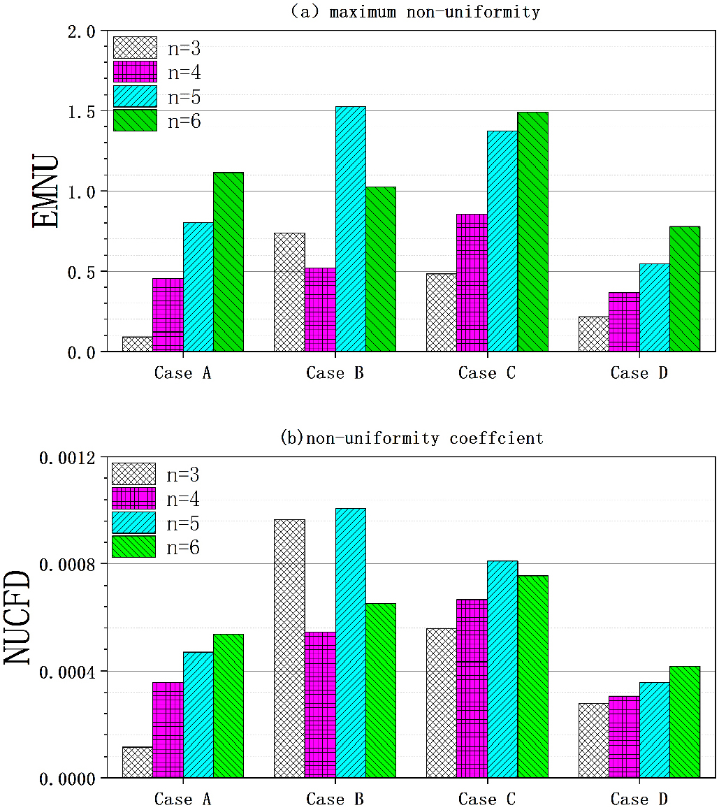
In order to investigate the effect of the outlet quantity on different manifolds, the number of outlet branches is changed by n = 3, 4, 5, and 6. Fig. 6 show streamlines with pressure contours and outlet mass flow rates for different number of outlet branches. Except for Case B, three type manifolds show outflow characteristics of the momentum dominant condition which the outlet mass flow rate increases with increasing the distance from the inlet. Even if n increases, this tendency remains unchanged. As can be seen, the vortex development of the manifold header has a strong influence on the outflow distributions. However, the flow distribution of the Case B manifold is characterized by the vortical regions in the outlet branches. From these flow characteristics, the non-uniformity of the outflow distribution is obtained. To evaluate global non-uniformities of the outlet flows, Fig. 7 shows MNU and NUCFD for different number of outlet branches. When the parameters become zero, a uniform distribution of outflow rates is obtained. Regardless of the manifold type, the outflow non-uniformity is strongly dependent on the number of outlet branches. As n increases, the outflow uniformities of all manifolds are reduced. However, for Case C, the outflow non-uniformity is improving somewhat when n increases from 5 to 6. Also, the outflow non-uniformity of Case D is the smallest for all cases except n = 3. From the results, an interesting relationship between the manifold type of Case B and the number of outlet branches is observed. Although the effect of the increased n is similar to the other three manifolds, the outflow non-uniformity is obtained differently depending on the odd or even number of branches. For Case B, the non-uniformity of the outlet flows is reduced for n = 4 and 6. Therefore, it is better that the number of outlet branches is increased by even numbers.
3.3 Effects of inlet Reynolds number
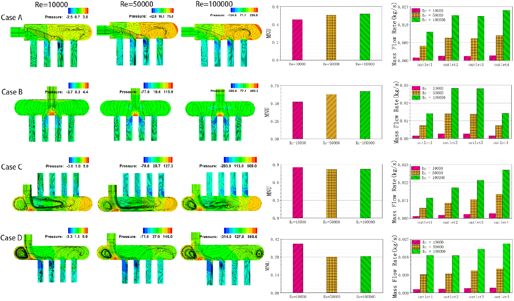
The inlet Reynolds number (Re) is an important variable in manifold design. As the inflow momentum changes, the pressure drop and the recirculating flow development can be different. Therefore, it is interesting to see the Re effects for four manifold types. Fig. 8 shows streamlines with pressure contours, MNU, and the mass flow rates of each outlet branch for different manifolds. Two cases of ReD = 10000, 50000, and 100000 are selected for n = 4. As can be seen, the distribution of the mass flow rates shows a significant difference depending on the manifold shape, because the flow development is strongly affected by the inlet arrangement. For Case A, the flow structures of the header regions are similar. As Re increases, a large vortex is generated in the header region near the last outlet. Also, the vortical regions near the junction region of header and outlet are expanded. Such expansion is significantly taking place in the first and second outlet. In a pipe flow, the vortical regions become generally an obstacle to streamwise flows. Based on this, the mass flow rates of third and fourth outlet are increased with increasing Re. For Case B, the inflow is divided into half and goes to the left and right branches and the second and third outlet branch have strong vortices. As Re increases, the vortical regions are generated in the outlet branches similar to Case A. For Case C and D, the vortex evolution in the outlets is similar to Case A, but the vortices in the header region are variously produced compared to Case A. As Re increases, the momentum dominant pattern is maintained for three types of Case A, C, and D. The outflow non-uniformity is increased for Case A and B, but reduced for Case C and D. Therefore, for manifold types of Case C and D, increasing the inlet velocity is advantageous for obtaining uniform outflows.
3.4 Effects of different inlet positions
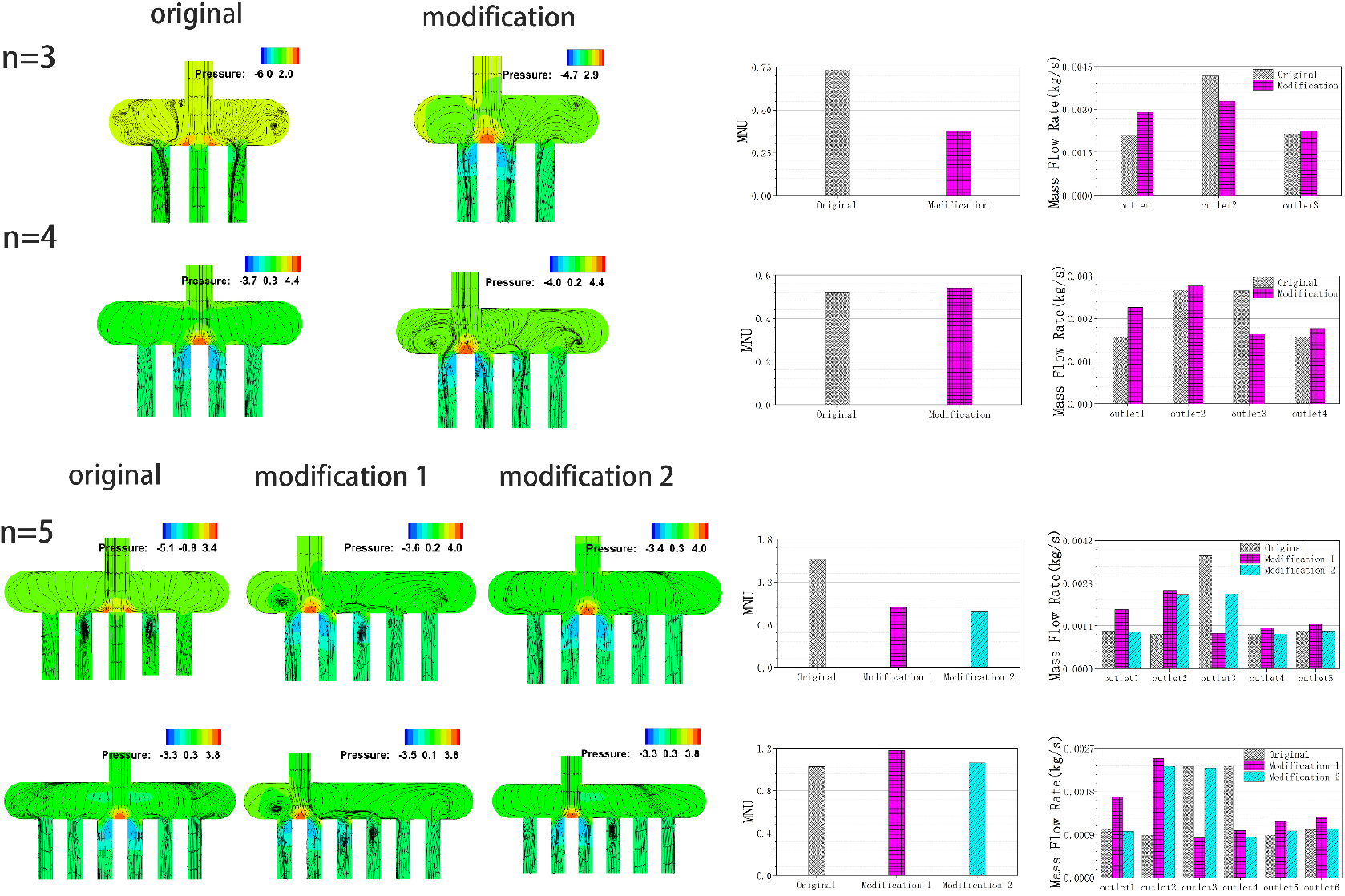
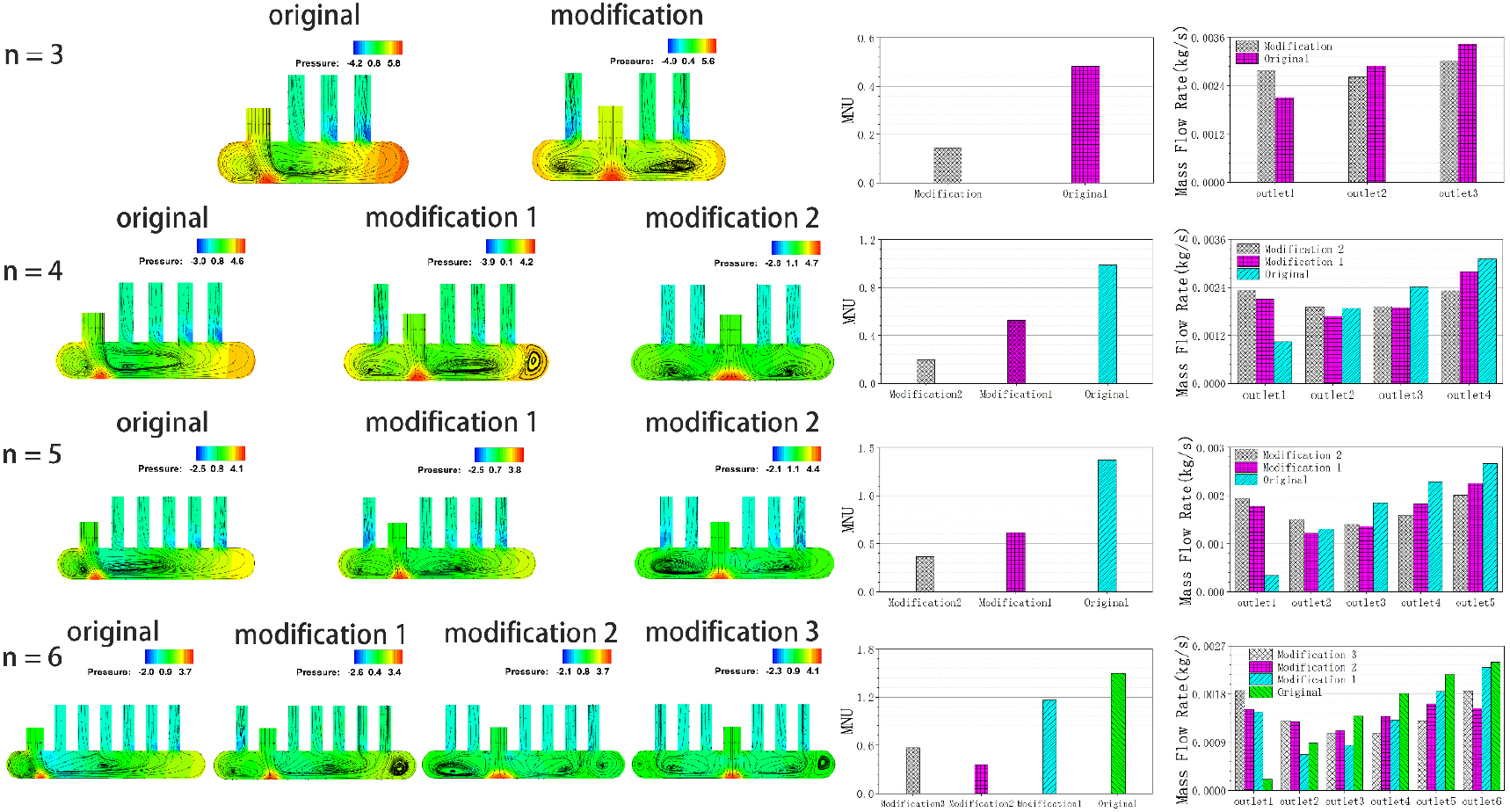
In the present study, Case B and D represent a bifurcation type manifold. As shown in Figs. 6, 7, the non-uniformity of Case B is worse than in other cases. In order to improve this feature, the change of the inlet position is studied. Fig. 9 shows streamlines with pressure contours, MNU, and outlet mass flow rates of Case B with different inlet. The inlet position is modified once for n = 3 and 4 and twice for n = 5 and 6. As can be seen, the movement of inlet position has little effect on n = 4 and 6, but has a significant effect on n = 3 and 5. For the case of odd channels, the flow distribution concentrated in the center outlet is relaxed due to the development of recirculation zones in the manifold header. As a result, the flow non-uniformity is also improving by 48% for n = 3 and 45% and 48% for modification 1 and modification 2 of n = 5. As previously discussed, the outflow non-uniformity of case B is not good for the odd number branches. It can be seen that this behavior is improved by modifying the inlet position. Additionally, the effect of the inlet position is also investigated for Case C. For the modified Case C with different inlet, Fig. 10 shows streamlines with pressure contours, MNU, and outlet mass flow rates. Unlike Case B, the change of the inlet position has a great effect on the improved non-uniformity of Case C. For different number of outlet branches, the improvement of MNU is estimated by 68% for n = 3, 45%~78% for n = 4, 54%~73% for n = 5, 16%~76% for n = 5. Therefore, it is confirmed that the outflow non-uniformity can be improved to the proper inlet position movement.
4. Conclusion
For different Depending on the different inlet position, four different manifolds of lateral inlet (Case A), central inlet (Case B), anti-parallel of inlet and outlet (Case C), parallel of inlet and outlet (Case D) are numerically studied for the outflow non-uniformity. The number of outlet branches, the inlet Reynolds number, and the movement of inlet position are considered. The vortical regions are differently formed by the relative location and arrangement of the inlet and outlet branches. The Case A manifold shows the excessive pressure recovery and the vortices in the outlet branch. The pressure drop of Case B is dominant at the outlet branches close to the inlet. For Case C, the pressure in the header region is recovered to the inlet pressure and a mixed feature of Case B and C is observed for Case D. The equilibrium state of friction and momentum forces is observed at Re = 100 for Case B and Re = 500~600 for the other three cases.
As the number of outlet branches increases, the outflow non-uniformities of all manifolds are increased. For Case B, the non-uniformity of the outlet flows is reduced for n = 4 and 6. Therefore, it is better that the number of outlet branches is increased by even numbers. The outflow non-uniformity of Case D is the smallest for all cases except n = 3. For manifold types of Case C and D, increasing the inlet velocity is advantageous for obtaining uniform outflows. Unlike Case B, the change of the inlet position has a great effect on the improved non-uniformity of Case D. For different number of outlet branches, the improvement of MNU is estimated by 68% for n = 3, 45%~78% for n = 4, 54%~73% for n = 5, 16%~76% for n = 5. The results confirm that the outflow non-uniformity can be improved to the proper inlet position movement.
